Contents: Removal ↳ Installation ↳
The exhaust manifold does not need to be removed. Removal is described for engines with a working volume of 2.4 and 2.9 liters. Attention is drawn to the differences for the engine with a working volume of 2.8 liters.
Please note: The 2.9L 24-valve engine (V6/24V, DOHC, Cosworth engine) is not included here.
Note: The signs by which a defective cylinder head gasket is determined are given on p. 15.
Removal
Disconnect the negative (-) battery cable.
Caution: When the battery is disconnected, the contents of electronic memory devices, such as engine fault codes or radio codes, are erased. Before disconnecting, also read the instructions in the chapter "Removal and installation the battery".
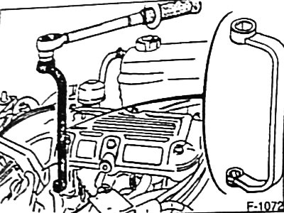
Disconnect the crankcase ventilation hose from the oil filler neck.
Drain the coolant, see p. 38.
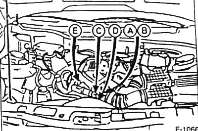
Disconnect the plug connectors or unscrew the fastening of all electrical wires going to the engine. To facilitate subsequent assembly, pre-mark the wires with adhesive tape.
- Plug connector of remote thermometer sensor "A".
- Plug connector of coolant temperature sensor "B".
- Plug connector for idle speed control valve "C".
- Throttle Position Sensor "D" Plug Connector.
- Combined plug connector for the wiring harness of the valve injectors "E".
- Multi-pin plug connector for ignition distributor.
Remove the air filter together with the suction hose, see p. 59.
Remove the gas rod.
Loosen the clamps and disconnect the heating system hose, the coolant hoses going to the expansion tank, and the upper radiator hose.
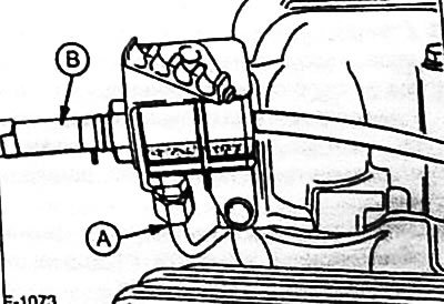
Engine with a working volume of 2.8 l: unscrew the fastening of the fuel supply line "A" to the pressure regulator. Loosen the clamp and disconnect the return fuel hose "B" from the pressure regulator.
Caution: To avoid fuel splashing, place clean cloth around fuel lines and loosen fasteners carefully to relieve pressure in the fuel system.
Engine with a working volume of 2.4 and 2.9 liters
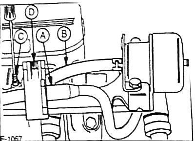
Using a screwdriver, release the fuel pressure through the air bleed valve "C". At the same time, cover the valve with a clean shaker.
Note: When the engine is warm, it is necessary to remove air from the system several times.
Disconnect the fuel supply line "A" using the special tool FORD 23-023-A.
Loosen the clamp and disconnect the fuel return hose "B".
Disconnect all vacuum hoses to the cylinder head. To facilitate subsequent assembly, mark the hoses with adhesive tape. Disconnect the vacuum hoses from:
- fuel pressure regulator
- mAP sensor air chamber
- eGR valves
- throttle bodies
- T-shaped fitting of the ventilation system valve cover
Remove 6 mounting bolts and remove the air chamber from the intake manifold.
Remove the spark plug caps, then remove the distributor cap.
Remove the ignition distributor, see p. 48.
Remove the V-belt, see p. 29.
Remove the generator, see p. 164.
Loosen the power steering pump bracket fastening and hang the pump with the attached hoses on a wire so that it does not interfere with further dismantling and so that the hoses are not subject to stretching.
Loosen the clamp and disconnect the coolant hose from the intake manifold end cover.
Remove the cylinder head cover.
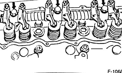
Loosen the rocker arm axle fasteners and remove them together with the oil catch can. Mark the rocker arm axles with a felt-tip pen so that they can be installed in their original places during assembly.
Caution: For a 2.9L engine equipped with a catalytic converter, the position of the adjusting screws in the rocker arms must not be changed.
Remove the push rods and place them so that they can be installed in their original places.
Remove the valve injectors complete with the wiring harness and fuel manifold, see p. 70.
Unscrew the 8 mounting bolts and remove the intake manifold. If the intake manifold cannot be removed, lift it with a lever.
Caution: Do not damage the sealing surfaces.
Loosen the fastening of the front exhaust pipe to the exhaust manifold, see p. 80.
Remove the spark plugs.
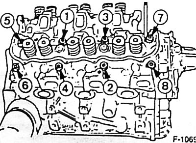
Loosen the cylinder head mounting bolts in sequence from 8 to 1 by about 1/2 turn, then unscrew the bolts completely. The right cylinder head is shown in the figure. For the left cylinder head, the operations are performed in the same sequence.
Caution: Loosening the bolts in the wrong sequence may result in warping or cracking of the cylinder head.
Check that all hoses and wires running from the cylinder heads to the engine and body are disconnected.
With the help of an assistant, remove the cylinder heads from the engine.
Caution: Do not place the removed cylinder heads directly on the sealing surface, as the fully open valves may be damaged. Place the cylinder heads on 2 wooden blocks.
Installation
Clean the sealing surfaces of the crankcase, intake manifold and cylinder heads from sealing residues using a suitable scraper. Do not scratch the sealing surfaces under any circumstances. Make sure that dirt does not get into the cylinder block openings. Cover the openings with rags.
Check the cylinder heads for cracks and the cylinder working surfaces for marks.
Check the cylinder head bolt holes for oil. If compressed air is not available to blow out the holes, use a small screwdriver to insert a clean rag into the holes to soak up the oil.
Note: Oil must be removed from the holes in any case.
The cylinder head gaskets must be replaced.
Caution: Install cylinder head gaskets in accordance with the OBEN FORN (TOP FRONT) marking. The gaskets for the right and left cylinder heads are not the same.
Place new cylinder head gaskets without sealant on the guide bushings so that they do not block any openings.
Install the cylinder heads.
New mounting bolts in the head and thread area are easy to lubricate and tighten by hand until tight.
Caution: Cylinder head mounting bolts must be replaced.
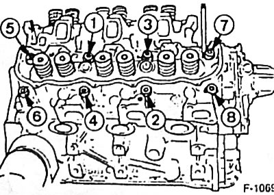
Tighten the cylinder head mounting bolts with a torque wrench in 3 stages. In each stage, tighten the bolts in sequence from 1 to 8.
Please note: Cylinder head bolts are available in two versions and are tightened to different torques.
Tightening torques for hexagon head bolts:
- Reception 1: 55 Nm
- Reception 2: 70 Nm.
- Reception 3: after a 15-minute break 115 Nm.
Note: After installation is complete and the engine has warmed up, the hexagon head bolts must be tightened to a torque of 115 Nm.
Tightening torques for bolts with internal slots in the head:
- Reception 1: 40 Nm.
- Reception 2: 75 Nm.
- Step 3: After a 5-minute pause, turn the locked key to an angle of 90°.
Note: After installation is complete and the engine has warmed up, do not tighten the bolts with internal slots in the head.
Caution: Tighten the cylinder head bolts very carefully. Before tightening, the torque wrench must be checked for accuracy. To facilitate tightening operations to a certain angle, a special protractor is required, for example, HAZET 6690. If a special protractor is not available, place the torque wrench on the bolt so that its handle is located along the cylinder head, mark the required angle using a regular protractor and make a corresponding mark on the cylinder head with chalk.
Install the front exhaust pipe, see p. 80.
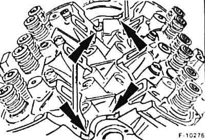
Thoroughly clean the joints between the crankcase and the cylinder heads at the flanges for the intake manifold (shaded in the figure) and apply FORD 85 TM 19554 AA sealant to them.
Install a new intake manifold gasket and intake manifold.
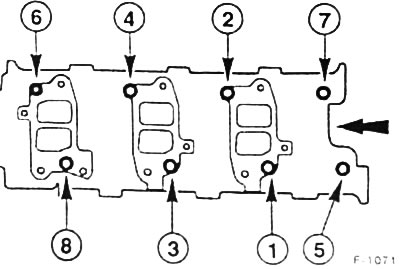
Tighten the intake manifold mounting bolts with a torque wrench in 4 stages. In each stage, tighten the bolts in sequence from 8 to 1.
- Reception 1: 8 Nm
- Reception 2: 15 Nm
- Reception 3: 20 Nm
- Reception 4: 25 Nm
Connect the coolant hose to the intake manifold end cover and secure it with a clamp.
The pushrods are easy to lubricate and insert into their original places in the crankcase holes. Make sure that the pushrods fit into the pushrod bearings.
Place the rocker arm axles together with the oil deflector and mounting bolts in accordance with the marks made before removal. At the same time, press the rocker arm adjusting screws to the spherical heads of the pushrods. Tighten the rocker arm axle mounting bolts to a torque of 70 Nm.
Caution: For a 2.9L engine equipped with a catalytic converter, the position of the adjusting screws in the rocker arms must not be changed.
Install the ignition distributor, see p. 48.
Engines with a working volume of 2.4 and 2.8 l: check the clearances in the valve drive, see p. 26.
Clean the joints between the cylinder heads and the intake manifold at the sealing surfaces for the cylinder head covers and apply FORD 85 TM 19554 AA sealant to them.
Glue the new sealing gaskets to the cylinder head covers with the adhesive side.
Place the cylinder head covers with sealing gaskets and tighten them to a torque of 10 Nm.
Screw in the spark plugs and tighten them to a torque of 40 Nm.
Install the distributor cap and install the spark plug caps in accordance with the cylinder firing order (1-4-2-5-3-6).
Install a generator, see p. 164.
Attach the power steering pump and tighten the bracket to 60 Nm.
Install the gas rod.
Install the V-belt, see p. 29.
Install the valve injectors complete with the fuel manifold and wiring harness. Tighten the fuel manifold mounting bolts to 10 Nm.
Note: Install the valve injectors with new sealing rings.
Place the air chamber with a new sealing gasket on the intake manifold and tighten the mounting bolts to 10 Nm. Connect the vacuum hose to the left cylinder head cover.
Connect and secure all electrical wires and vacuum hoses as marked prior to removal.
2.8L engine: screw the fuel supply line to the pressure regulator. Connect the fuel return hose to the pressure regulator and secure it with a clamp.
2.4 and 2.9 L engines: connect the fuel supply line to the plastic ring on the supply pipe that centers the coil spring. If the connection is secured, the ring pops out. Connect the fuel return hose and secure it with a clamp.
Connect the crankcase ventilation hose to the oil filler cap.
Connect and secure with clamps the coolant hoses going to the heating system, expansion tank and upper radiator hose.
Install the air filter together with the suction hose, see p. 59.
Check the engine oil level and top up if necessary. If the cylinder head gasket is damaged, replace the engine oil and oil filter, as the engine oil may contain coolant.
Check the concentration of antifreeze in the coolant and add coolant, see p. 38.
Connect the battery ground (-) cable.
If available, set the clock and enter the radio theft protection code.
Engines with a working volume of 2.4 and 2.9 l: turn on the ignition and remove air from the fuel system through valve "C" (see figure F-1067). To do this, push the valve with a screwdriver until fuel flows through it.
Check and, if necessary, adjust the ignition timing angle, see p. 50.
Check and, if necessary, adjust the engine crankshaft speed at idle see p. 64.
Warm up the engine to operating temperature, check the engine oil and coolant levels and check all hose connections for leaks.
Engine with cylinder head fastening with hexagonal head bolts after reaching operating temperature (at coolant temperature of approximately +90°C), stop the engine and loosen the cylinder head cover fastening. Tighten the cylinder head fastening bolts in the sequence shown in Figure F-1069 to a torque of 115 Nm. Tighten the cylinder head cover fastening.
With the engine warmed up to operating temperature (with a coolant temperature of approximately +90°C), tighten the intake manifold mounting bolts to a torque of 25 Nm. At the service station, a special FORD 21-144 tool is used for this. If this tool is not available, it is necessary to unscrew the air chamber mount and, after tightening the bolts, reinstall it with a new sealing gasket.