Contents: Removal ↳ Installation ↳
The petrol engine is removed without the gearbox by moving it upwards. The intake and exhaust manifolds, as well as the generator, do not need to be dismantled. A crane is required to remove the engine. The diesel engine is removed together with the gearbox, so before removing it, also read the chapter "Removal and installation the gearbox". Since some connections must be released from the underbody side, four reliable stands are required, as well as a garage jack to lift the car. Before installation work in the engine compartment, it is necessary to close the body fenders with covers.
Depending on the year of manufacture and the vehicle's equipment, electrical wires, as well as vacuum and coolant hoses, may be located differently in the engine compartment. Since it is impossible to specify each option individually, it is recommended to mark the appropriate wire with adhesive tape before removal. The following describes the removal of a 4-cylinder DOHC engine manufactured before 8/92.
Removal
Disconnect the negative (-) battery cable.
Caution: When the battery is disconnected, the contents of electronic memory devices, such as engine fault codes or radio codes, are erased. Before disconnecting, also read the instructions in the chapter "Removal and installation the battery".
Remove the engine compartment hood, see p. 132.
Remove the air filter together with the suction hose, see p. 57.
Drain the engine oil, see section "Maintenance".
Car with air conditioning: remove the V-belt, see p. 29.
Drain the coolant, see p. 38.
Disconnect the upper and lower coolant hoses from the radiator, first loosening the mounting clamps.
Loosen the mounting clamps and disconnect all coolant hoses leading to the expansion tank.
Loosen the clamp and disconnect the heating system hose at the coolant pump.
Depending on the engine: disconnect the second heating system hose at the cylinder head, at the intake manifold or at the cover of the automatic fuel mixture enrichment device when starting. Loosen the fastening clamp beforehand.
V6 engine: loosen the fan impeller fastening, see p. 41.
Loosen the fastener and remove the radiator air guide shroud, see the chapter "Removing and installing the radiator".
V6 Engine: Remove Radiator, see p. 42.
Remove the gas rod.
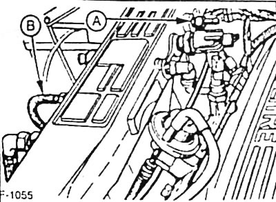
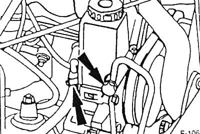
4-cylinder engine with injection system: disconnect the vacuum hoses from the MAP sensor "A" and the activated carbon container "B". To facilitate subsequent assembly, pre-mark the hoses with adhesive tape.
Carburetor engine: Disconnect the vacuum hose from the control unit.
If equipped, disconnect the vacuum hoses from the A/C compressor and automatic transmission.
Disconnect the ventilation system hose at the cylinder head cover.
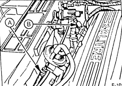
Fuel injection engine: Loosen the clamps and disconnect the fuel hoses from the pressure accumulator "A" and the fuel line "B". Before disconnecting, shake the connectors to prevent fuel from splashing. Quickly plug the fuel lines with suitable plugs. To do this, insert, for example, clean bolts with a thread of the appropriate diameter into the hoses. To facilitate subsequent assembly, mark the hoses with adhesive tape in advance. Caution: Disconnect the fuel hoses carefully so that the pressure in the fuel system can be released.
Carburetor engine Loosen the clamps and disconnect the fuel hoses at the carburetor and at the fuel pump. Disconnect the plug connectors or unscrew the fastening of all electrical wires going to the engine. To facilitate subsequent assembly, pre-mark the wires with adhesive tape.
- Multi-pin generator plug connector.
- Combination plug connector for fan motor.
- Plug connector for crankshaft speed/position sensor (CPS).
- Engine with injection system: oxygen sensor plug connector.
- Fuel injection engine, combined plug connector for engine management system wiring harness.
- Engine with injection system: combined plug connector for valve injectors.
- Carburetor engine: plug connector for automatic fuel mixture enrichment device at start-up.
- Carburetor engine: Intake manifold heating element plug connector.
- Carburetor engine combination plug connector stepper motor carburetor.
- Coolant Temperature Sensor Plug Connector
- Combined plug connector for ignition distributor.
- Plug connector for coolant temperature switch.
- Hydraulic switch plug connector.
Vehicle with power steering: disconnect the pressure line and hose to the expansion tank at the power steering pump. Place a container underneath and collect the leaking fluid.
4-cylinder engine OHC: remove the engine oil level sensor from the engine crankcase.
Raise the car onto the trestles.
If equipped, remove the lower engine compartment cover.
Car with air conditioning system
Warning. Do not open the refrigerant circuit of the air conditioning system. The refrigerant contains substances that can cause frostbite if they come into contact with the skin. The engine can be removed without opening the refrigerant circuit.
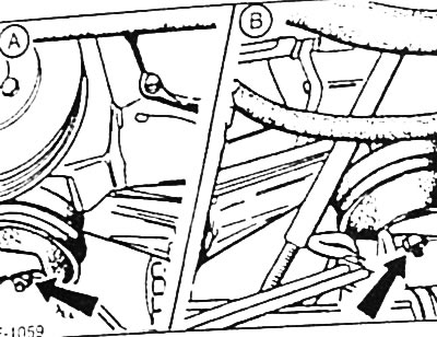
Unscrew the bolts securing the "arrow" and hang the air conditioning system compressor with the attached hoses on a wire so that it does not interfere with further removal, and the hoses are not subject to stretching.
Unscrew the fastening of the front exhaust pipe to the exhaust manifold. Disconnect the exhaust system from all holders and remove, see p. 80.
Remove the starter, see p. 167.
Vehicle with automatic transmission: through the hole for the starter in the clutch housing, unscrew the 4 bolts "arrow" of the torque converter. To turn the engine crankshaft, put a ratchet mechanism with a suitable sprocket on its belt pulley.
Car with manual transmission: unfasten the clutch drive rod or, accordingly, disconnect the hydraulic drive from the gearbox, see p. 84.
V6 engine: remove oil filter, see p. 198.
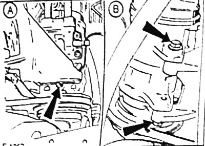
4-cylinder ONO engine and V6 engine: Unscrew bolt "A" securing the engine intermediate plate.
4-cylinder engine OHC: unscrew the bolts "arrows" securing the gearbox coupler.
Remove all bolts securing the clutch housing flange. Disconnect the ground wire, the positive wire holder, and for vehicles with an automatic transmission, the oil filler tube, as well as the vacuum line holder.
Disconnect the brake pipes from the holders on the left and right of the front axle.
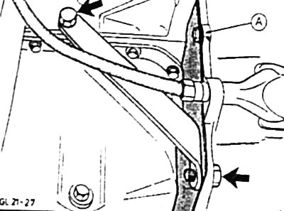
Loosen the nuts "arrows" securing both engine mounts (A - right side of the engine B - left side of the engine).
Loosen the locking pins of the "arrow" on the left and right of the connecting post so that the pins still fit tightly in the thread of the side member.
Support the gearbox with a garage jack.
Check that all hoses and wires between the engine and the body are disconnected.
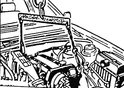
Insert the ends of the lifting device into the engine suspension eyes, lift the engine lightly with a crane and pull it forward. Disconnect the engine from the gearbox with a strong shaking motion. Pull the engine out of the engine compartment with an upward movement.
Installation
Check engine mounts, coolant, oil and fuel hoses for porosity and cracks, replace them with new ones if necessary.
Check the ease of movement of the bearing and clutch release lever; replace defective parts if necessary.
Check the thickness and condition of the clutch driven disk linings. Replace the clutch disk if necessary.
Clean the splines of the gearbox drive shaft and treat with MoS2 grease.
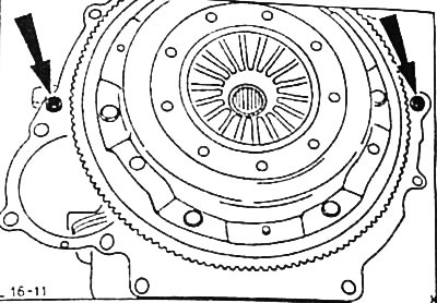
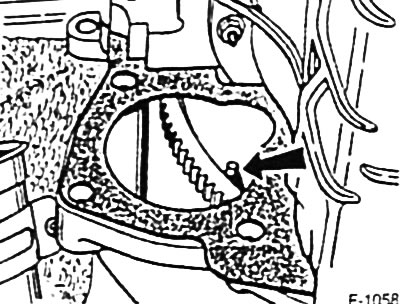
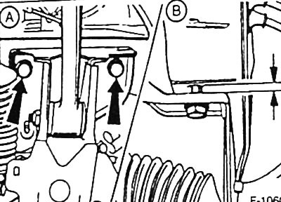
Check whether the engine block crankcase contains both guide bushings "arrows". If necessary, pull the guide bushings out of the clutch housing and hammer them into the engine block crankcase.
Place the intermediate plate on the guide bushings and glue it to the crankcase in several places using grease.
Note: If there were spacers in the oil pan area, they must be installed in the same position as they were before removal.
Lower the engine into the engine compartment. When lowering, make sure that the gearbox drive shaft enters the splines of the driven clutch disk. If the shaft does not enter the splines of the driven clutch disk, use a ratchet mechanism to turn the engine crankshaft on the belt pulley.
Using shaking movements, move the engine towards the gearbox so that there is a gap of approximately 5 mm between their housings. Screw in 2 bolts until their heads touch the flange of the clutch housing.
Lower the engine completely, ensuring that its supports are correctly positioned on the bridge beam. Unfasten the engine lifting device.
Lower the garage jack under the gearbox and remove it.
Screw in all the bolts securing the clutch housing flange. Connect the ground wire, the positive wire holder, and for a car with an automatic transmission, the oil filler tube, as well as the vacuum line holder.
Tighten the engine mounting bolts to the gearbox to a torque of 40 Nm.
4-cylinder OHC engine and V6 engine: attach the engine intermediate plate and tighten the fastening to a torque of 10 Nm.
4-cylinder engine OHC: attach the gearbox clamp and tighten the mounting bolts.
Car with manual transmission: attach the clutch drive rod or connect the hydraulic drive to the gearbox, respectively, see p. 84.
Vehicle with automatic transmission: through the starter hole in the clutch housing, screw in the 4 converter mounting bolts and tighten them to a torque of 40 Nm.
Tighten the connecting post locking pins to a torque of 90 Nm.
Tighten the engine mount mounting nuts to a torque of 70 Nm.
Install the starter, see p. 167.
Install the exhaust system assembly, see p. 80.
Car with air conditioning system: attach the air conditioning compressor and tighten the mounting bolts to a torque of 75 Nm.
If equipped, install the lower engine compartment cover.
Lower the car.
A car with power steering.
Connect the hose from the power steering pump to the expansion tank and secure it with a clamp.
Attach the pressure line to the power steering pump and tighten the fastening to a torque of 30 Nm.
4-cylinder engine OHC: insert the engine oil level sensor into the engine block.
Connect and secure all electrical wires and vacuum hoses in accordance with the marks applied.
Install the gas rod.
V6 Engine: Install Radiator, see p. 42.
V6 Engine: Install Fan Wheel, see p. 41.
Place the air guide casing against the radiator and tighten the fastening to a torque of 10 Nm.
Connect the coolant hoses and secure them with clamps
Connect the coolant hoses to the expansion tank and secure them with clamps.
Connect the heating system hoses and secure them with clamps.
Connect the fuel inlet and outlet hoses in accordance with the marks and secure them with clamps.
Connect the engine ventilation hose to the cylinder head
* Vehicle with air conditioning system: install V-belt, see p. 29.
Install the air filter together with the suction hose, see p. 57.
V6 Engine: Install Oil Filter, see p. 198.
Add motor oil to the engine, see p. 198.
A car with a power steering, add hydraulic fluid to the hydraulic drive expansion tank and remove air from the hydraulic drive, see p. 108.
Check the concentration of antifreeze in the coolant and pour it into the cooling system, see p. 200.
Install the engine compartment hood, see p. 132.
Connect the battery ground (-) cable.
If available, set the clock and enter the radio theft protection code.
Check and, if necessary, adjust the ignition timing angle, see p. 50.
Carburetor engine: check and, if necessary, adjust the engine idle speed and CO content, see p. 64.
Warm up the engine to normal operating temperature, check the levels of working fluids and check the connection points of all hoses for leaks.
[This publication was borrowed from the website: FordBook.ru]