Vehicle wiring diagrams Ford Fusion

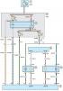
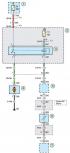
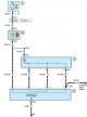
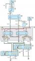
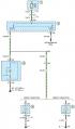
Scheme 1. Block diagram of the car
Block diagram of the car 1 - ignition switch (lock); 2 - mounting block in the engine compartment; 3, 4 - relay and fuse box behind the glove compartment; 5 - fuel pump...
Block diagram of the car 1 - ignition switch (lock); 2 - mounting block in the engine compartment; 3, 4 - relay and fuse box behind the glove compartment; 5 - fuel pump...
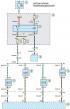
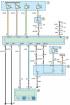
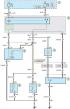
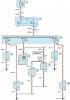
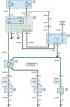
Scheme 2. Engine management system
Scheme 2a. Engine management system 1 - fuse box in the engine compartment; 2 - relay and fuse box behind the glove compartment; 3 - relay of the electronic engine...
Scheme 2a. Engine management system 1 - fuse box in the engine compartment; 2 - relay and fuse box behind the glove compartment; 3 - relay of the electronic engine...
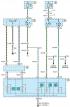
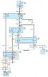
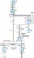
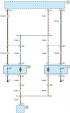
Scheme 3. Power supply system
Power supply system 1 - mounting block in the engine compartment; 2 - relay and fuse box behind the glove compartment; 3 - relay for disabling the air conditioning...
Power supply system 1 - mounting block in the engine compartment; 2 - relay and fuse box behind the glove compartment; 3 - relay for disabling the air conditioning...

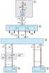
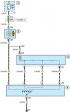
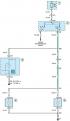
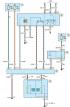
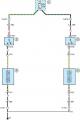
Scheme 4. Engine starting system for cars with manual transmission
Scheme 4a. Engine starting system for cars with manual transmission 1 - ignition switch (lock); 2 - relay and fuse box behind the glove compartment; 3 - starter relay; 4...
Scheme 4a. Engine starting system for cars with manual transmission 1 - ignition switch (lock); 2 - relay and fuse box behind the glove compartment; 3 - starter relay; 4...
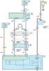
Diagram 5. Charging system
Scheme 5a. Charging system 1, 5 - relay and fuse box behind the glove compartment; 2 - battery; 3 - instrument cluster; 4 - starter; 6 - electronic engine control unit;...
Scheme 5a. Charging system 1, 5 - relay and fuse box behind the glove compartment; 2 - battery; 3 - instrument cluster; 4 - starter; 6 - electronic engine control unit;...
Scheme 6. Ignition system
Scheme 6. Ignition system 1 - fuse box in the engine compartment; 2 - ignition coil; 3 - spark plugs; 4 - electronic engine control unit; 5 - camshaft position sensor; 6...
Scheme 6. Ignition system 1 - fuse box in the engine compartment; 2 - ignition coil; 3 - spark plugs; 4 - electronic engine control unit; 5 - camshaft position sensor; 6...

Scheme 7. Car audio system
Scheme 7. Car audio system 1 - electronic engine control unit; 2 - electronic control unit of the immobilizer; 3 - relay and fuse box behind the glove compartment; 4 -...
Scheme 7. Car audio system 1 - electronic engine control unit; 2 - electronic control unit of the immobilizer; 3 - relay and fuse box behind the glove compartment; 4 -...
Scheme 8. Cooling system
Scheme 8a. Cooling system 1 - fuse box in the engine compartment; 2 - relay and fuse box behind the glove compartment; 3 - Engine cooling system fan relay; 4 - Electric...
Scheme 8a. Cooling system 1 - fuse box in the engine compartment; 2 - relay and fuse box behind the glove compartment; 3 - Engine cooling system fan relay; 4 - Electric...

Diagram 9. Robotic gearbox
Scheme 9a. Robotic gearbox 1 - relay and fuse box behind the glove compartment; 2, 6 - fuse box in the engine compartment; 3 - control unit of the robotic gearbox; 4 -...
Scheme 9a. Robotic gearbox 1 - relay and fuse box behind the glove compartment; 2, 6 - fuse box in the engine compartment; 3 - control unit of the robotic gearbox; 4 -...
Scheme 10. Anti-lock braking system (ABS) and dynamic stabilization system (ESP)
Scheme 10a. ABS and ESP 1, 4 - relay and fuse box behind the glove compartment; 2 - additional brake light; 3 - Dynamic Stabilization Control Unit (ESP); 5 - built-in...
Scheme 10a. ABS and ESP 1, 4 - relay and fuse box behind the glove compartment; 2 - additional brake light; 3 - Dynamic Stabilization Control Unit (ESP); 5 - built-in...

Scheme 11. Diagnostic connector
Scheme 11a. Diagnostic connector 1 - relay and fuse box behind the glove compartment; 2 - ignition switch (lock); 3 - audio system; 4 - audio and navigation system...
Scheme 11a. Diagnostic connector 1 - relay and fuse box behind the glove compartment; 2 - ignition switch (lock); 3 - audio system; 4 - audio and navigation system...

Scheme 12. Anti-theft system
Scheme 12a. Anti-theft system 1 - relay and fuse box behind the glove compartment; 2 - instrument cluster; 3 - electronic control unit of the immobilizer; 4 - left front...
Scheme 12a. Anti-theft system 1 - relay and fuse box behind the glove compartment; 2 - instrument cluster; 3 - electronic control unit of the immobilizer; 4 - left front...

Scheme 13. Illumination of the combination and instrument panel
Scheme 13. Illumination of the combination and instrument panel 1, 2, 8, 9 - relay and fuse box behind the glove compartment; 3 - Outdoor lighting switch; 4, 7 -...
Scheme 13. Illumination of the combination and instrument panel 1, 2, 8, 9 - relay and fuse box behind the glove compartment; 3 - Outdoor lighting switch; 4, 7 -...
Scheme 14. Instrument cluster and steering column switches
Scheme 14a. Instrument cluster and steering column switches 1, 2 - relay and fuse box behind the glove compartment; 3 - steering column switch for exterior lighting; 4 -...
Scheme 14a. Instrument cluster and steering column switches 1, 2 - relay and fuse box behind the glove compartment; 3 - steering column switch for exterior lighting; 4 -...

Scheme 15. Sound signal
Scheme 15. Sound signal 1 - sound signal key; 2 - spiral spring; 3 - relay and fuse box behind the glove compartment; 4 - electronic control unit of the immobilizer; 5 -...
Scheme 15. Sound signal 1 - sound signal key; 2 - spiral spring; 3 - relay and fuse box behind the glove compartment; 4 - electronic control unit of the immobilizer; 5 -...

Scheme 16. Clock in the car interior
Scheme 16. Clock in the car interior 1 - relay and fuse box behind the glove compartment; 2 - instrument cluster
Scheme 16. Clock in the car interior 1 - relay and fuse box behind the glove compartment; 2 - instrument cluster
Scheme 17. Heating and ventilation system
Scheme 17. Heating and ventilation system 1 - relay and fuse box behind the glove compartment; 2 - electric motor of the ventilation and air conditioning system of the...
Scheme 17. Heating and ventilation system 1 - relay and fuse box behind the glove compartment; 2 - electric motor of the ventilation and air conditioning system of the...
Scheme 18. Air conditioning system
Scheme 18a. Air conditioning system 1 - relay and fuse box behind the glove compartment; 2 - electric motor of the ventilation and air conditioning system of the...
Scheme 18a. Air conditioning system 1 - relay and fuse box behind the glove compartment; 2 - electric motor of the ventilation and air conditioning system of the...
Scheme 19. Interior lighting of the salon
Scheme 19a. Interior lighting of the salon 1 - relay and fuse box behind the glove compartment; 2 - electronic control unit of the immobilizer; 3 - front interior light;...
Scheme 19a. Interior lighting of the salon 1 - relay and fuse box behind the glove compartment; 2 - electronic control unit of the immobilizer; 3 - front interior light;...
Scheme 20. Daytime driving lights (DRL system)
Scheme 20a. Daytime running lights (DRL system) 1 - ignition switch (lock); 2, 5, 8 - relay and fuse box behind the glove compartment; 3 - External lighting switch...
Scheme 20a. Daytime running lights (DRL system) 1 - ignition switch (lock); 2, 5, 8 - relay and fuse box behind the glove compartment; 3 - External lighting switch...
Scheme 21. Fog lights
Scheme 21. Fog lights 1 - relay and fuse box behind the glove compartment; 2 - External lighting switch block; 3 - instrument cluster; 4 - left fog light; 5 - right fog...
Scheme 21. Fog lights 1 - relay and fuse box behind the glove compartment; 2 - External lighting switch block; 3 - instrument cluster; 4 - left fog light; 5 - right fog...
Scheme 22. Car headlights
Scheme 22a. Car headlights 1, 6 - relay and fuse box behind the glove compartment; 2 - External lighting switch block; 3 - left steering column switch; 4 - fuse box in...
Scheme 22a. Car headlights 1, 6 - relay and fuse box behind the glove compartment; 2 - External lighting switch block; 3 - left steering column switch; 4 - fuse box in...
Scheme 23. Side lights and number plate illumination
Scheme 23. Side lights and number plate illumination 1, 3 - relay and fuse box behind the glove compartment; 2 - External lighting switch block; 4 - left headlight; 5 -...
Scheme 23. Side lights and number plate illumination 1, 3 - relay and fuse box behind the glove compartment; 2 - External lighting switch block; 4 - left headlight; 5 -...
Scheme 24. Reversing lights for cars with manual transmission
Scheme 24. Reversing lights for vehicles equipped with a manual or robotic gearbox 1 - relay and fuse box behind the glove compartment; 2 - Reversing light switch; 3 -...
Scheme 24. Reversing lights for vehicles equipped with a manual or robotic gearbox 1 - relay and fuse box behind the glove compartment; 2 - Reversing light switch; 3 -...

Scheme 25. Car brake lights
Scheme 25a. Car brake lights 1 - relay and fuse box behind the glove compartment; 2 - brake light switch; 3 - additional brake light; 4 - right rear light; 5 - left rear...
Scheme 25a. Car brake lights 1 - relay and fuse box behind the glove compartment; 2 - brake light switch; 3 - additional brake light; 4 - right rear light; 5 - left rear...
Scheme 26. Direction indicators
Scheme 26a. Direction indicators 1, 3 - relay and fuse box behind the glove compartment; 2 - left steering column switch; 4 - hazard warning switch; 5 - electronic...
Scheme 26a. Direction indicators 1, 3 - relay and fuse box behind the glove compartment; 2 - left steering column switch; 4 - hazard warning switch; 5 - electronic...
Scheme 27. Rear fog lights
Scheme 27. Rear fog lights 1 - relay and fuse box behind the glove compartment; 2 - External lighting switch block; 3 - instrument cluster; 4 - left rear light; 5 -...
Scheme 27. Rear fog lights 1 - relay and fuse box behind the glove compartment; 2 - External lighting switch block; 3 - instrument cluster; 4 - left rear light; 5 -...

Scheme 28. External rear view mirrors
Scheme 28a. External rear view mirrors 1, 3, 4 - relay and fuse box behind the glove compartment; 2 - switch for adjusting the outside rearview mirrors; 5 - left outside...
Scheme 28a. External rear view mirrors 1, 3, 4 - relay and fuse box behind the glove compartment; 2 - switch for adjusting the outside rearview mirrors; 5 - left outside...

Scheme 29. Car windshield washer
Scheme 29. Car windshield washer 1 - relay and fuse box behind the glove compartment; 2 - right steering column switch; 3 - windshield washer pump electric motor; 4 -...
Scheme 29. Car windshield washer 1 - relay and fuse box behind the glove compartment; 2 - right steering column switch; 3 - windshield washer pump electric motor; 4 -...
Scheme 30. Heating of the rear door glass and mirrors
Scheme 30. Heating of the rear door glass and mirrors 1, 4 - relay and fuse box behind the glove compartment; 2 - electronic control unit of the immobilizer; 3 - heating...
Scheme 30. Heating of the rear door glass and mirrors 1, 4 - relay and fuse box behind the glove compartment; 2 - electronic control unit of the immobilizer; 3 - heating...

Scheme 31. Lock drive
Scheme 31. Lock drive 1 - relay and fuse box behind the glove compartment; 2 - remote control; 3 - instrument cluster; 4 - electronic control unit of the immobilizer
Scheme 31. Lock drive 1 - relay and fuse box behind the glove compartment; 2 - remote control; 3 - instrument cluster; 4 - electronic control unit of the immobilizer
Scheme 32. Central lock
Scheme 32. Central lock 1, 4 - electronic control unit of the immobilizer; 2 - left rear door lock module; 3 - Right rear door lock module
Scheme 32. Central lock 1, 4 - electronic control unit of the immobilizer; 2 - left rear door lock module; 3 - Right rear door lock module
Scheme 33. Seat heating
Scheme 33. Seat heating 1 - relay and fuse box behind the glove compartment; 2 - Left front seat heating switch; 3 - Right front seat heating switch; 4 - Left front seat...
Scheme 33. Seat heating 1 - relay and fuse box behind the glove compartment; 2 - Left front seat heating switch; 3 - Right front seat heating switch; 4 - Left front seat...
This section is available on russian, bulgarian, belarusian, ukrainian, serbian, croatian, romanian, polish, slovak, hungarian
See other similar sections for Ford cars:
• Electrical equipment: Electrical circuits Ford Focus Turnier 1 (1998-2004)
• Electrical equipment: Electrical circuits Ford Mondeo 1 (1993-1996)
• Electrical equipment: Electrical circuits Ford Escort 4 (1986-1990)
• Electrical equipment: Electrical equipment diagrams Ford Fiesta 2 (1983-1989)
• Electrical equipment: Electrical circuits Ford Transit 2 (1986-2000, diesel)
Fusion
Scorpio 1
Scorpio 2
Sierra
- General information
- Vehicle device
- User manual
- Faults on the way
- Maintenance
- Tips for the car owner
- Power unit
- Engine repair
- Lubrication and cooling system
- Supply system
- Exhaust and vapor recovery
- Transmission
- Clutch
- Car gearbox
- Front wheel drives
- Chassis
- Front suspension
- Rear suspension
- Steering
- Brake system
- Wheels and tires
- Body
- Exterior
- Interior
- Doors, locks and windows
- Body сare
- Electrical equipment
- Equipment and devices
- Engine electrics
- Lighting and signaling
- Switches and sensors
- Electrical circuits
Scorpio 1
- General information
- User manual
- Maintenance
- Power unit
- Petrol engines OHC
- Petrol engines DOHC
- Petrol engines V6
- Ignition and control
- Diesel engines
- Cooling system
- Supply system
- Carburetors
- Fuel injection
- Transmission
- Clutch
- Manual gearbox «N»
- Manual gearbox «MT 75»
- Automatic gearbox «A4LD»
- Rear axle and drive shafts
- Chassis
- Steering
- Power steering
- Front suspension
- Rear suspension
- Brake system
- Body
- Exterior
- Interior
- Doors, locks and windows
- Heating and ventilation
- Electrical equipment
- Equipment and devices
- Power devices
- Electrical circuits
Scorpio 2
- General information
- Car care
- Maintenance
- Power unit
- Engine repair
- Lubrication system
- Cooling system
- Ignition system
- Supply system
- Carburetors
- Injection system (gasoline)
- Injection system (diesel)
- Exhaust system
- Transmission
- Clutch
- Car gearbox
- Chassis
- Front suspension
- Rear suspension
- Steering
- Brake system
- Wheels and tires
- Body
- Exterior
- Interior
- Doors, locks and windows
- Heating system
- Electrical equipment
- Equipment and devices
- Headlights and lighting
- Windshield wipers and washers
- Power devices
- Electrical circuits
Sierra
- General information
- User manual
- Maintenance
- Gasoline engines
- Engine repair
- Ignition system
- Fuel system
- Cooling and lubrication system
- Changes 1984-1986
- Changes 1987-1989
- Changes 1990-1993
- Diesel engines
- Engine repair
- Fuel system
- Cooling and lubrication system
- Changes 1988-1993
- Transmission
- Clutch
- Mechanical gearbox
- Automatic gearbox
- Cardan and rear axle
- Chassis
- Steering
- Steering with power steering
- Front suspension
- Rear suspension
- Brake system
- Body and electrical
- Body elements and doors
- Electrical equipment
- Electrical circuits