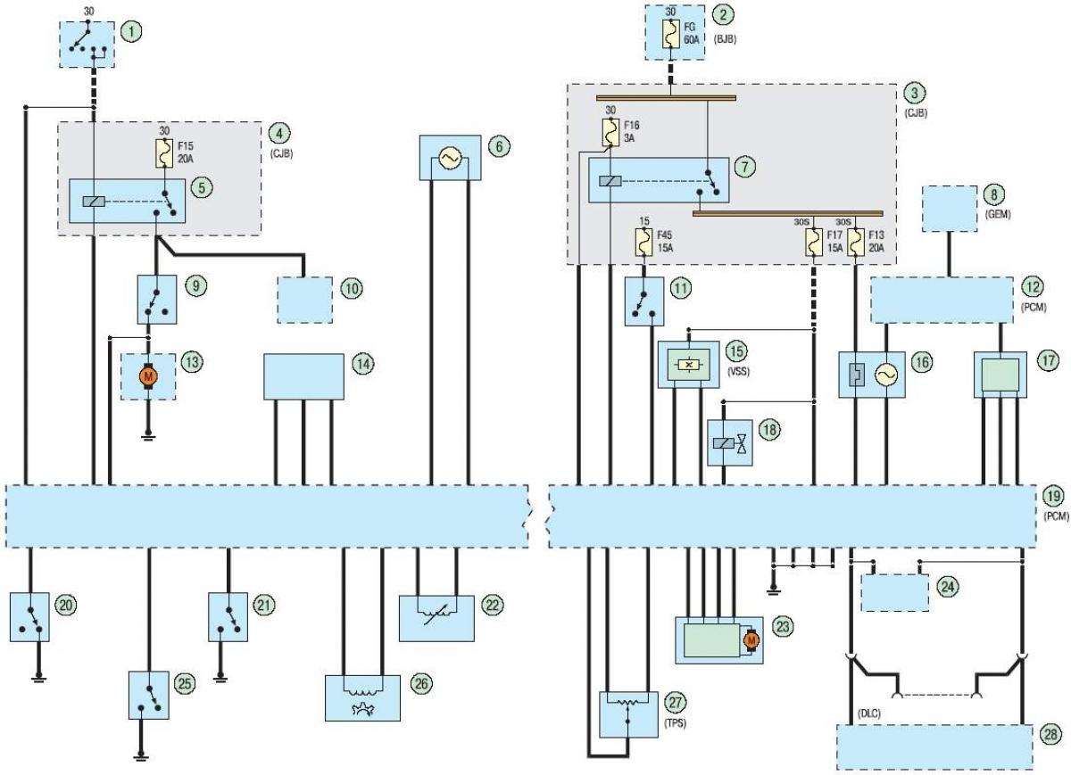
Block diagram of the car
Open large image in new tab »
1 - ignition switch (lock); 2 - mounting block in the engine compartment; 3, 4 - relay and fuse box behind the glove compartment; 5 - fuel pump relay; 6 - knock sensor; 7 - Electronic engine control unit relay; 8 - electronic control unit of the immobilizer; 9 - emergency fuel supply switch; 10 - ignition coil; 11 - additional brake light; 12, 19 - electronic engine control unit; 13 - fuel pump module; 14 - accelerator pedal position sensor; 15 - wheel speed sensor; 16 - control and diagnostic oxygen concentration sensors; 17 - absolute pressure sensor in the intake manifold; 18 - Evaporative Emissions Blow-off Solenoid Valve; 20 - power steering fluid pressure sensor; 21 - brake pedal position sensor; 22 - coolant temperature sensor; 23 - idle speed control electric motor; 24 - Anti-lock braking system (ABS) control unit; 25 - Clutch pedal position sensor; 26 - camshaft position sensor; 27 - throttle position sensor; 28 - instrument cluster
The original text is provided on an online resource FordBook