Contents: Cleaning ↳ Inspection ↳
Note: Always check first what parts are available before planning any action. A Ford dealer or a good engine repair specialist may be able to offer you alternatives that will overcome the shortage of parts if there is a problem.
Cleaning
1. Before cleaning, remove all internal and external components and sensors as previously described. Additionally, if the cylinder block is to be sent for machining, remove the rear camshaft cover (see Figure 15.1,a), as well as the fuel cap of the pressure reducing valve of the lubrication system, the sealing ring, the spring and the plunger (see Figure 15.1, b, c, d, e).
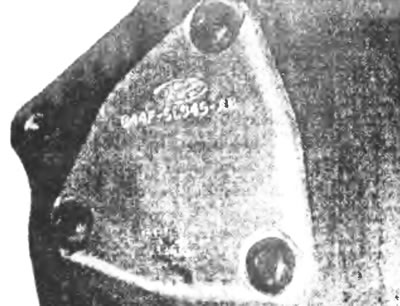
Figure 15.1a. Remove the rear camshaft thrust plate...
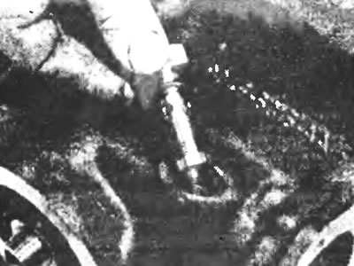
Figure 15.1b....the head of the pressure-reducing valve of the lubrication system with a sealing ring...
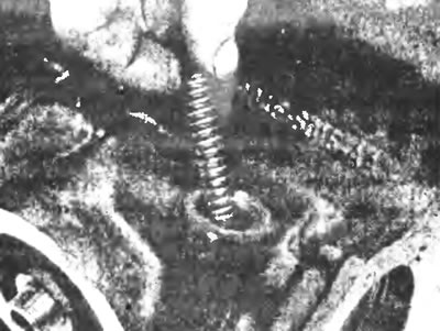
Figure 15.1c....a release spring.
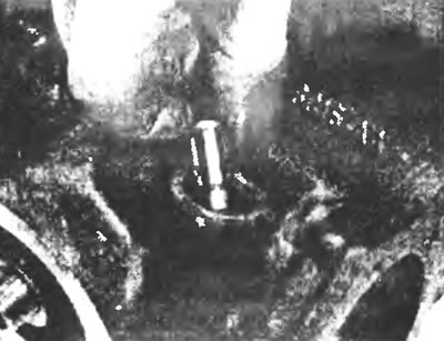
Figure 15.1g.... and the valve plunger.
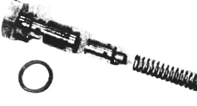
Figure 15.1d. Details of the pressure-reducing valve of the lubrication system.
2. Inspect all cylinder block channel plugs for signs of corrosion or aging. If such signs are detected, the plugs must be replaced. Drill a small hole in the center of each plug and pull them out with an automotive plug puller or similar tool.
3. If any of the parts is heavily soiled, it should be cleaned with steam.
4. Once all parts have been steam cleaned, drain all oil and fuel passages, allow to dry and apply a thin film of oil to all working surfaces to prevent rust. If you have access to compressed air, use it to speed up the drying process.
Warning: Protect your eyes when using compressed air!
5. If the parts are not very dirty, you can wash them with hot soapy water (almost boiling water!) and a stiff brush. Don't be lazy! Regardless of the cleaning method you use, make sure you thoroughly clean and dry all oil and fuel ports. Protect work surfaces as described above.
6. All threaded holes must be clean and dry to ensure accurate tightening torque data during assembly. Screw a tap of the proper size into each of the holes to remove rust, corrosion and repair damaged threads (see Figure 15.6). If possible, use compressed air to clean the holes of any dirt produced by this action; you can also inject a dispersion aerosol lubricant into each hole using a long stream.
Warning: Be careful not to expose your eyes to the cleaning fluid when cleaning the holes this way and make sure there is no excess liquid in the holes.
7. When the inspection and repair are completed (see below) and the cylinder block is ready for assembly, insert suitable plugs into the holes in the block. Make sure they are positioned correctly so that leakage is impossible. There are special tools, but if you don't have them, you can use an extension, a hammer, and a socket head, the outer diameter of which should be slightly smaller than the diameter of the channel into which the plug needs to be inserted.
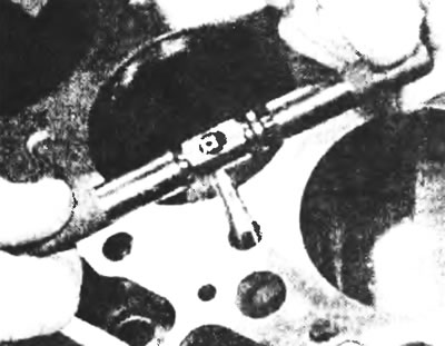
Figure 15.6. Clean all threaded holes in the cylinder block with marks of the corresponding sizes.
8. Install all other external remote components, referring to the relevant chapters of this manual as necessary. Install the bearing caps and tighten the bolts hand tight. Also install the rear camshaft cover using new parts such as the gasket, fuel pressure relief valve cap, O-ring, spring and plunger.
9. If the engine is not reassembled immediately after disassembly, cover it with a large plastic bag to keep it clean and protect the working surfaces as described above to prevent rust.
Inspection
10. Inspect surfaces for cracks and corrosion. Check the threaded connections. If there has been any coolant leak, you must contact a specialist to search for cracks in the cylinder block and crankcase using special equipment. If defects are found, repair, if possible, or replace the cylinder block and crankcase with new ones.
11. Make sure that the inner surface of the cylinders is not damaged or nicked.
12. Measure the inside diameters of the cylinders, securing all the crankshaft main bearing shells with bolts (without crankshaft and bearing shells), to the tightening torque value specified in the specification, recording the diameter values of each cylinder at the top (under the ridge area), in the center and at the base of the cylinder, parallel to the crankshaft axis. Next, measure the diameter of each cylinder at the same three locations across the crankshaft axis (see Figure 15.12). Write down the obtained dimensions.
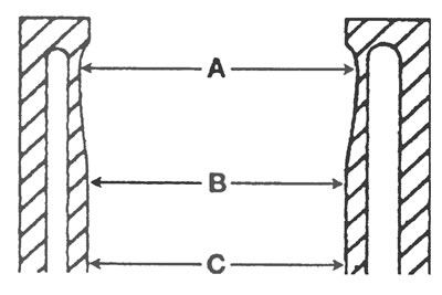
Figure 15.12. Measure the diameter of each cylinder just below the wear ridge (A), at the center (B), and at the bottom of the cylinder (C).
13. Measure the piston diameter at right angles to the piston pin axis, just above the base of the skirt, and record the results (see Figure 15.13).
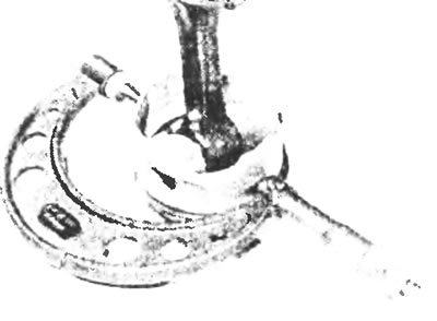
Figure 15.13. Measure the piston skirt diameter on the axis perpendicular to the piston pin directly above the base.
14. To obtain the piston clearance in the cylinder, measure the cylinder bore diameter and the piston skirt as described above, and subtract the skirt diameter from the bore diameter. If the high-precision measuring instruments described above are not available, the condition of the pistons and cylinders can be assessed, although not very accurately, with feeler gauges as follows. Select a feeler gauge with a thickness equal to the specified piston clearance in the cylinder and insert it into the cylinder next to the corresponding piston. The piston must be placed exactly as it is normally placed. The piston must slide through the cylinder (with a feeler gauge in place) with moderate pressure, if it falls through or slides too easily, the play is too large, the piston must be replaced. If the piston is stuck at the bottom of the cylinder and free at the top, the cylinder is tapered. If, when rotating the feeler gauge blade around the piston in the cylinder, the feeler gauge gets stuck in some places, then the cylinder has lost its round shape.
15. Repeat these procedures for the remaining pistons and cylinders.
16. Compare the results with the Specifications at the beginning of this Chapter if any measurement is outside the specification limits, or if any of the six cylinder diameter measurements differs significantly from the others (an indication that the hole diameter is tapered or oval), either the piston or the cylinder is excessively worn.
17. If any of the cylinders is significantly larger or smaller than the others, or if it is excessively worn, out of round, or tapered, the worn cylinder is usually bored out and a corresponding new one is installed during rebuilding (oversized) piston. Consult your Ford dealer or engine repair specialist before performing this procedure.
18. If the cylinder liners are in good condition and not excessively worn, then only the piston rings may need replacing.
19. When replacing piston rings, the cylinder should be bored so that the new rings fit correctly and provide the best seal. Before you begin boring, install the main bearing caps (without liners), and tighten the bolts to the specified torque.
Remember: if you don't have the right tools, or don't want to do the boring yourself, most auto repair shops will be happy to do it for a reasonable fee.
20. For boring, along with the traditional honing head, you can use special honing heads for cylinders of two types - "flex" and "bottle-brush". Both of these heads are equally suitable, but for the beginning mechanic, the honing head "bottle-brush" will probably be easier to use. You will also need a rag and some paraffin or kerosene. Proceed as follows:
a) Install the honing head into the drill, compress it and insert it into the first sleeve to be bored. Be sure to wear protective glasses or a mask.
b) After generously lubricating the inside diameter of the cylinder with oil, turn on the drill and run the honing head up and down the inside of the cylinder liner, which will produce light cross-hatching strokes on its walls. Ideally, the crossed lines form an angle of 50°-60° (see Fig. 15.20). Make sure you use enough lubricant and do not remove more metal than necessary.
Please note: Piston ring manufacturers may specify different crosshatch angles - follow the instructions supplied with new rings.
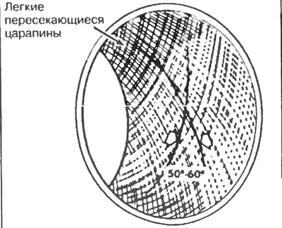
15.20. The honing head should leave light scratches on the cylinder mirror, intersecting at an angle of approximately 60°.
c) Do not remove the honing head from the sleeve while it is working. After turning off the drill, continue to move it up and down the sleeve until it stops completely, then squeeze the sharpening stones and remove the head. If you are using a head type "bottle-brush", then, after turning off the drill, turn the clamp in the normal direction and pull it out of the sleeve,
d) After wiping the cylinder mirror from oil, repeat the procedure for the remaining cylinders;
d) When the liners of all cylinders have been bored, remove the chamfer from the upper edges of the liners with a small file so that the rings do not get stuck when installing the pistons. Be very careful not to make nicks in the cylinder walls with the end of the file,
e) The crankcase and cylinder block must be washed very thoroughly with warm soapy water to remove any abrasive sand formed during honing.
Note: Cartridges can only be considered clean when they are wiped (not lint-free) if you wipe it with a white cloth soaked in clean motor oil, you will not find any dirt on it. Make sure to clean all oil holes and channels with a brush and rinse with running water;
g) When the crankcase and cylinder block are completely clean, rinse and dry them, then lightly oil all surfaces to prevent corrosion.
21. Now that the crankcase and cylinder block are completely clean and dry, all components are checked for wear or damage and repaired or replaced with new ones as necessary. Install auxiliary elements as described above (see paragraphs 7 and 8). If you do not begin rebuilding immediately, cover the block with a large plastic bag to keep it clean and protect the work surfaces from rusting.
(For more information, please visit the website: Fordbook.ru)