Contents: Cleaning ↳ Inspection ↳
Note: Always check first what parts are available before planning any major repairs. Ford dealer or a good engine repair specialist (spare parts supplier), may be able to offer alternatives that will allow you to overcome the shortage of spare parts if there is a problem.
1. A complete cleaning of the cylinder head and valve train components, accompanied by a detailed inspection, will allow you to determine the amount of valve maintenance work required during a major engine overhaul.
Note: If the engine has been severely overheated, the cylinder head should be carefully checked for warpage.
Cleaning
2. Remove all traces of old gasket material, carbon deposits or sealant from the cylinder head, then wash the head thoroughly with paraffin or a suitable solvent.
3. Remove any heavy carbon deposits that have formed on the valves.
4. Use a special wire brush to remove carbon deposits from the valve heads and stems.
Inspection
Note: Be sure to complete all of the following inspection procedures before concluding that the services of a machine shop or engine overhaul specialist are required. Make a list of all the items that require attention.
Cylinder head
5. Inspect the head very carefully for cracks that indicate coolant leakage or other damage. If cracks are found, the cylinder head must be replaced.
6. Use a straight edge and feeler gauge to check that the cylinder head gasket surface is not distorted (see Figure 10.6). If this is the case, it may be possible to fix it with polishing. If the manufacturer has not provided data on the permissible warpage value, then it can be assumed that if the value exceeds 0.15 mm over the entire length, then the warpage is too great.
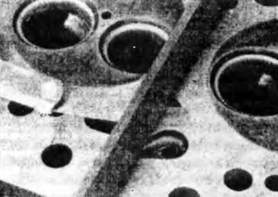
Figure 10.6 Using a feeler gauge and a straight edge, check that the cylinder head gasket is not deformed.
7. Inspect the valve seats in each combustion chamber. If they are heavily pitted, cracked or burned, then they must be replaced or mechanically lapped by an engine overhaul specialist. If they are only slightly pitted, this can be corrected by lapping the heads and valve seats with a special compound as described below.
8. If the valve guides are worn when the valve moves from side to side, the guides must be replaced. Measure the valve stem diameters (see below) and the guide bore diameter, then calculate the clearance and compare the result with the specification value: if the clearance is excessive, replace the valves or guides with new ones as necessary.
9. It is better to leave the replacement of valve guide bushings to a specialist in engine overhaul.
10. If the valve seats need to be lapped, this should only be done after replacing the guides.
Valves
11. Inspect all valve heads for pits, gouges, cracks and general wear, and check the valve stems for wear ridges and nicks. Rotate the valve and check for any signs that it is not bent. Look for pitting and excessive wear on the tip of each valve stem. Replace any valve that shows any signs of wear or damage with a new one.
12. If the valve appears satisfactory at this stage, measure the valve stem diameter at several points using a micrometer (see Figure 10.12). Any significant difference in the data obtained indicates valve stem wear. If any of these conditions are evident, the valve should be replaced.
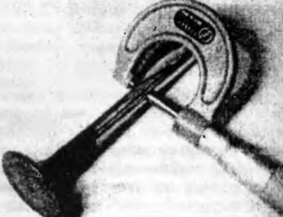
Figure 10.12. Measure the valve stem diameter in several places with a micrometer.
13. If the valves are in satisfactory condition, they should be installed in their respective seats to ensure gas tightness. If the seat is only slightly worn, use a light grinding compound to bring it into good condition. Coarse valve grinding compound should not be used unless the seat is badly burned and deeply pitted; if this is the case, the cylinder head and valves should be inspected by an expert to determine whether it is better to lap the seats or install new valves and seats.
14. Lapping is carried out as follows: Place the cylinder head upside down on two blocks to provide free space for the valve stems.
15. Apply the appropriate grade of grinding compound to the face of the seat and press the grinding tool onto the valve head. Using a semi-rotary action, grind the valve head onto the seat, occasionally removing the valve to redistribute the grinding compound (see figure 10.15, a, b) A light spring placed under the valve head will make this operation much easier.
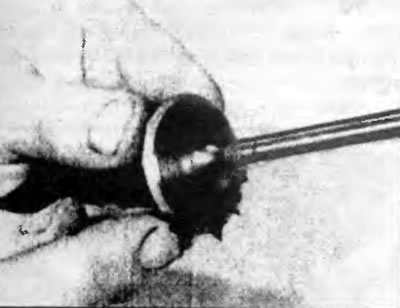
Figure 10.15,a. Apply valve grinding compound to the valve bezel...
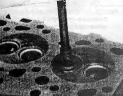
Figure 10.15, b. Then, using a semi-rotational motion, grind the valve to the seat.
16. If using a coarse sanding compound, sand the valve seat and valve only until a matte finish is achieved, then wipe off the compound and repeat the process with a light compound. When you have a smooth, unbroken ring of a light matte gray color on the valve and seat, finish sanding. Do not grind the valves more than necessary, otherwise the seat will drop below the cylinder head level.
17. Once all the valves have been lapped, carefully wash them to remove all traces of the grinding compound using paraffin or a suitable solvent.
Valve components
18. Inspect the valve springs for signs of damage and discoloration and measure their free length using a vernier caliper (see Figure 10.18).
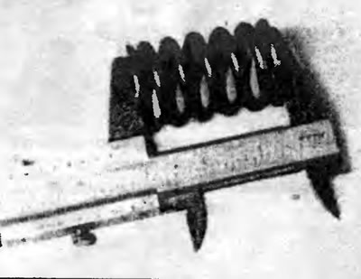
Figure 10.18. Measure the free length of the valve spring with a caliper.
19. Place each spring on a flat surface and check for perpendicularity (see Figure 10.19). If any of the springs are damaged, distorted, or have lost tension, purchase a complete set of new springs.
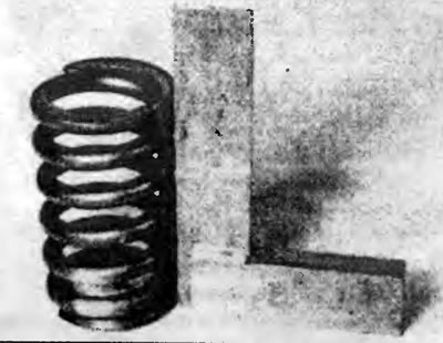
Figure 10.19. Using a square, check the spring for perpendicularity.
20. Check the valve seats and cracks for wear and cracks. Replace any questionable parts, as extensive damage to the engine will occur if any part fails while it is running. All damaged or excessively worn parts must be replaced; valve stem oil seals must be replaced whenever they are removed.
21. Check the valve train components as described in Part A of this Chapter.