Contents: Removal ↳ Installation ↳
Special tool
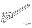 | Universal Flange Holding Wrench 205-072 (15030A) |
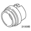 | Oil Seal Remover 303-039 (21-009B) |
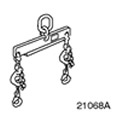 | Engine Lifting Tool 303-122 (21068A) |
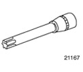 | Cylinder Head Bolt Socket Wrench 303-392 (21-167) |
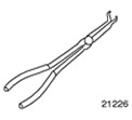 | Spark Plug Pliers 303-622 (21-226) |
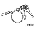 | Radiator Hose Clamp Remover and Installer 303-397 (24-003) |
General equipment:
- Spatula
- Wooden block
- Rolling jack
- Repair zone crane
| Name | Specification |
| Sealant for camshaft bearing caps | WSK-M2G348-A5 |
| Sealant | WSK-M4G348-A5 |
| Sealant remover | WSK-M2G348-A4 |
| Motor oil | WSS-M2C912-A1 |
| Silicone grease for spark plug connector seals | A960-M1C171-AA |
Removal
1. General instructions:
- The position of the engine mounts and engine tilt limiters in the description corresponds to the view directed from the gearbox towards the engine.
- If necessary, use special tool 303-397 to remove coolant and ventilation hoses.
- Due to the existence of different variants of the same car model, some working steps are not applicable to all cars. In such cases, this is clearly stated in the text.
2. Standard preparatory activities:
- Please mark the radio key code.
- Mark the preset radio stations.
CAUTION: Disconnect the ground cable from the battery.
- If necessary, cut the clamps and install new ones during installation.
3. Drain the coolant. Refer to Section 303-03 for additional information.
4. Remove the timing belt. For more information, refer to the Timing Belt chapter in this section.
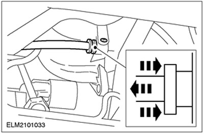
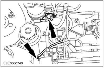
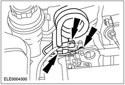
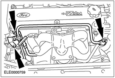
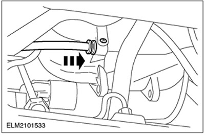
5. Disconnect the brake booster line and PCV hose from the intake manifold.
- Release the quick release coupling and disconnect the brake booster line.
- Disconnect the positive crankcase ventilation hose.
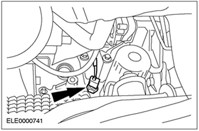
6. Disconnect the oil pressure switch connector.
7. Lower the vehicle.
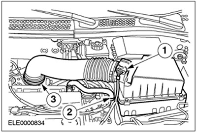
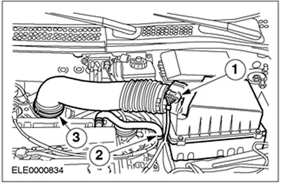
8. Remove the air filter housing.
- 1. Disconnect the mass air flow (MAF) sensor connector.
- 2. Disconnect the PCV hose.
- 3. Disconnect the inlet hose.
- Remove the air filter housing from the rubber bushing.
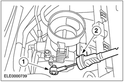
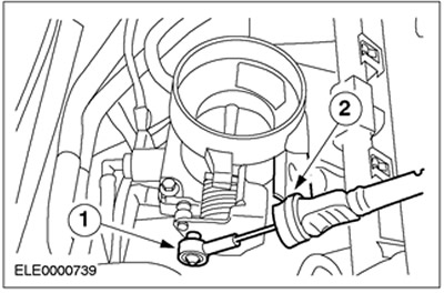
9. Disconnect the accelerator cable.
- 1. Unhook the cable.
- 2.Remove the plastic clamp and set the accelerator cable aside.
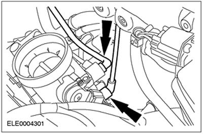
10. Disconnect the low pressure hoses.
11. Disconnect the wiring harness connector and the cylinder head temperature (CHT) sensor connector.
12. Relieve the fuel pressure. Refer to Section 310-00 for additional information.
13.
WARNING: Fuel leakage. Handle fuel with care.
Disconnect the fuel lines. Disconnect the ground wire.
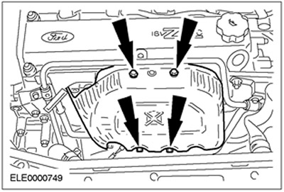
14. Remove the heat shield.
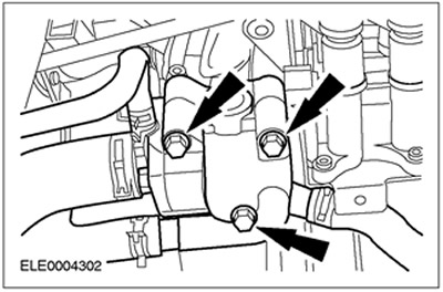
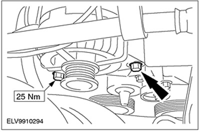
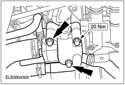
15. Disconnect the thermostat housing.
16. Disconnect the catalytic converter from the exhaust manifold.
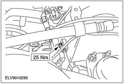
17. Disconnect the power steering pipe bracket and the dipstick tube.

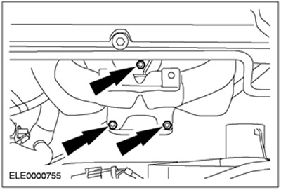
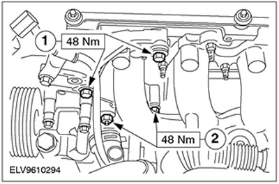
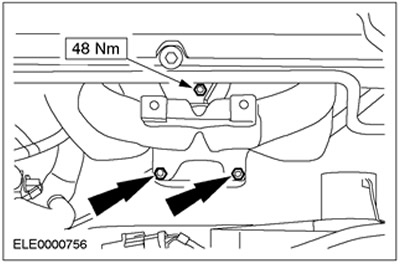
18. Remove the power steering pump bracket.
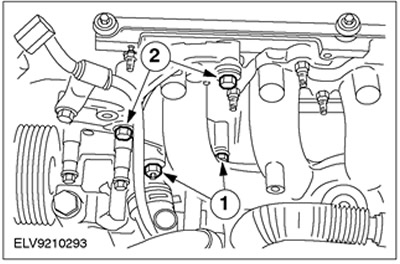
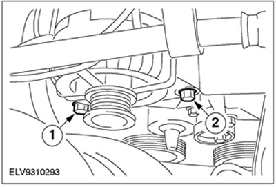
19. Disconnect the generator.
- 1. Unscrew the bolt.
- 2. Unscrew the bolt.
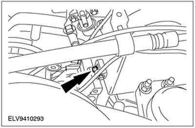
20. Remove the top bolt from the generator bracket.
21.
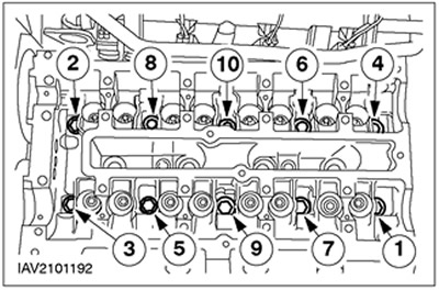
NOTE: Follow the release sequence.
Loosen the camshaft bearing cap bolts, working evenly in several stages, loosening two turns at a time.
- Remove the oil seals.
- Remove the camshafts.
- Remove the pushers and arrange them in order.
22.
CAUTION: Mark bolts to be reused by punching one or two marks on them with a center punch. Bolts can be reused twice. If necessary, discard bolts as no longer needed.
CAUTION: The cylinder head must be cooled to outside temperature.
NOTE: Follow the release sequence.
Remove the cylinder head bolts.
23. Remove the cylinder head and set it aside on a clean surface.
Installation
1. General notes: If necessary, use special tool 303-397 to remove coolant and ventilation hoses.
2. Preparatory operations:
CAUTION: Do not damage the cylinder liner. Remove carbon deposits from the top edge of the cylinder.
- Remove all traces of sealant using a sealant remover and putty knife.
- Thoroughly clean the threaded holes for the cylinder head bolts.
3. Inspect the cylinder head for warpage. Refer to Section 303-00 for additional information.
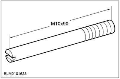
4. Make guide pins according to the drawing.
5.
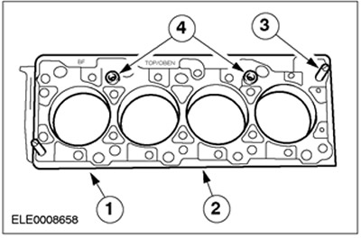
CAUTION: Cylinder head gasket selection depends on the cylinder block casting number.
Install a new cylinder head cover gasket onto the cylinder block.
- 1.Cylinder block number
- 2.Install a new cylinder head gasket.
- 3.Install the prefabricated dowel pins.
- 4. Check that the guide pins are installed correctly.
6. Install the cylinder head. Check the position of the cylinder head on the cylinder block.
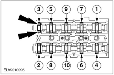
7.
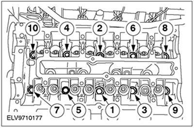
CAUTION: Do not overtighten the cylinder head bolts.
Tighten the cylinder head bolts using special tool 303-392, working in three stages in the sequence shown.
- Stage 1: 20 Nm
- Stage 2: 40 Nm
- Stage 3: 90 degrees
- Apply engine oil to the lifters and install them in the same order they were removed.
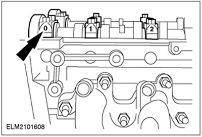
8. Apply sealant to the bearing caps of camshafts No.0 and 5 in the indicated locations.
9. Turn the crankshaft to approximately 60 degrees before top dead center for cylinder #1.
10.
NOTE: Identification numbers are located on the outside of the camshaft bearing caps.
Install the camshafts so that none of the lobes are in the full lift position. Apply engine oil to the camshafts and camshaft bearing caps.
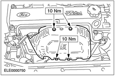
11.
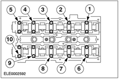
NOTE: Install the camshaft bearing cap bolts, working evenly in several stages, in the sequence shown, one-half turn at a time, and then tighten them in two stages.
Tighten the camshaft bearing cap bolts.
- Stage 1: 10 Nm
- Stage 2: 19 Nm
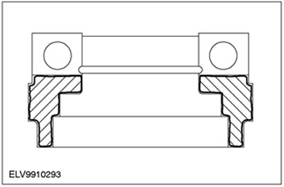
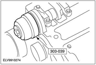
12. Install the camshaft oil seals.
- Apply engine oil to the camshafts and oil seal lips.
- Install a new oil seal. Use a special tool, washer and bolt M10x70.
NOTE: Do not tighten the bolts. The camshaft pulleys must be able to turn freely on the camshafts. Install the pulleys.
13. Install the timing belt. For more information, refer to the Timing Belt chapter in this section.
14. Lower the vehicle.
15. Install the power steering pump bracket.
- 1.Install the top bolt.
- 2.Install the lower studs.
- Tighten the bolts and nuts.
16. Install the top bolt onto the generator bracket.
17. Connect the generator.
18. Install the dipstick tube and power steering line bracket.
19. Connect the catalytic converter to the exhaust manifold.
20. Connect the thermostat housing. Use a new gasket.
21. Install the heat shield.
22. Connect the fuel lines.

23. Connect the plug connector of the engine wiring harness and the plug connector of the SNT sensor.

24. Connect the accelerator cable.
- 1. Hook the cable in the required position.
- 2.Install the plastic clamp.
25. Connect the vacuum hoses.

26. Install the air filter housing.
- Install the air filter housing into the rubber grommets.
- 1. Connect the mass air flow sensor (MAF sensor) connector.
- 2.Connect the crankcase ventilation hose.
- 3.Connect the inlet hose.
27. Raise the vehicle. Refer to Section 100-02 for additional information.
28. Connect the oil pressure switch plug connector.

29. Connect the brake booster hose and PCV hose to the intake manifold.
30. Standard finishing operations:
- Connect the ground wire to the battery.
- Fill with coolant. Refer to Section 303-03 for additional information.
- Close the expansion tank of the cooling system.
- Check the fluid levels and adjust them if necessary.
- Check the routing of vacuum hoses, cables and wires and secure them using clamps.
- Enter the radio key code.
- Reprogram preset radio stations.
- Set the clock.
- Perform a road test to allow the PCM to collect data.
- Check the fluid levels again and adjust them if necessary.
NOTE: Engine oil temperature must be at least 80°C.
- Change the engine oil and oil filter. For more information, refer to the General Specifications chapter in this section.