Special tool
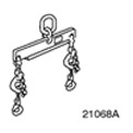 | Engine Lifting Tool 303-122 (21068A) |
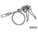 | Radiator Hose Clamp Remover and Installer 303-397 (24-003) |
General equipment:
- Assembly table
- Fixing clamp
- Lift
- Wooden blocks
| Name | Specification |
| Clamps | |
| High temperature grease | ESD-M1C220-A |
All cars
1. Replace the locknuts and retaining ring. If necessary, use special tool 303-397 to install and remove the coolant hoses and vent hoses.
2. Preparatory operations:
- Using the locking clamp, install the gearbox onto the assembly stand.
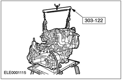
- Secure the engine to the hoist, position it in the desired position relative to the gearbox and support it using wooden blocks.
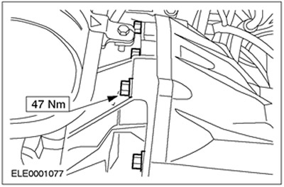
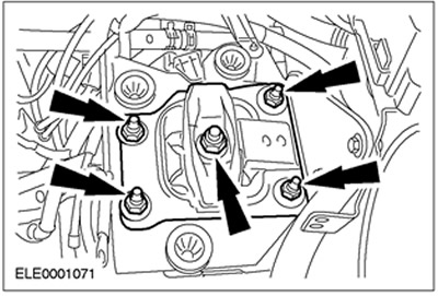
3. Tighten the flange bolts.
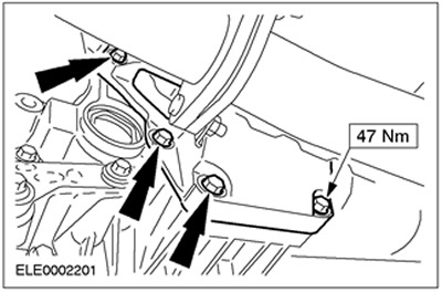
4. Tighten the flange bolts (continued).
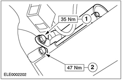
5. Install the starter and tighten the flange bolt.
- 1.Starter bolt
- 2.Flange bolt
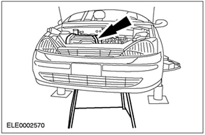
6. Raise the vehicle. Refer to Section 100-02 for additional information.
7. Place the engine and gearbox assembly, secured on the assembly stand, under the vehicle. Carefully lower the vehicle.
8.
NOTE: Hand tighten the bolts and nuts.
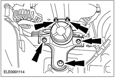
Install the front engine mount.
9.
NOTE: Hand tighten the nuts.
Install the rear engine mount.
10.
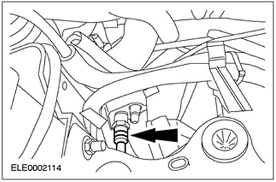
CAUTION: Brake fluid leakage. Handle brake fluid safely. Refer to Section 206-00 for additional information.
Connect the high pressure line of the clutch slave cylinder.
11. Remove the retaining clamp from the gearbox.
12. Raise the vehicle. Refer to Section 100-02 for additional information. Remove the assembly stand.
13. Install the engine roll limiter.
14.
CAUTION: The inner hinge should not be adjusted more than 18 degrees, and the outer hinge should not be adjusted more than 45 degrees.
NOTE: Use new bolts and a new intermediate bearing cap.
Install the right half shaft of the front drive axle together with the intermediate shaft.
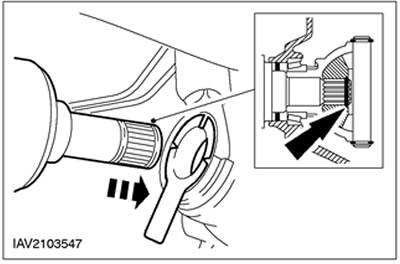
15.
NOTE: Ensure that the snap ring is properly secured.
Insert the left half shaft of the front drive axle together with the new retaining ring into the gearbox.
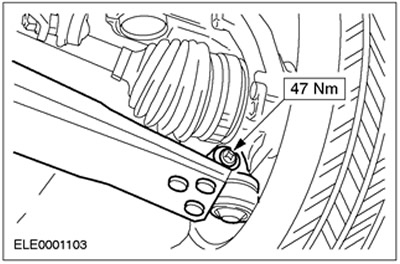
16. Connect both suspension arms (right side shown).
17. Install both front wheels. For additional information, refer to Section 204-04.
18. Install the flexible exhaust pipe.
19. Lower the vehicle.
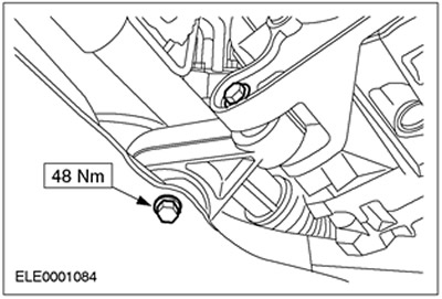
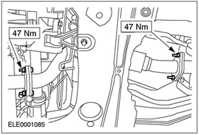
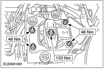
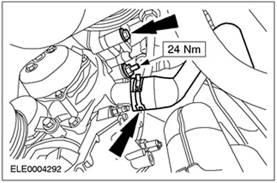
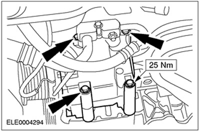
20. Tighten the rear engine mount nuts/bolts.
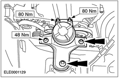
21. Tighten the front engine mount nuts.
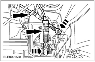
22. Install the power steering pump and tighten the upper bolts.
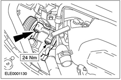
23. Connect the bracket for the power steering high pressure line.
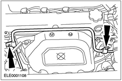
24. Connect the PAS tank.
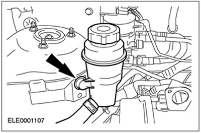
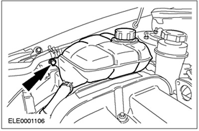
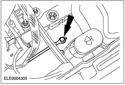
25. Install the expansion tank of the cooling system.
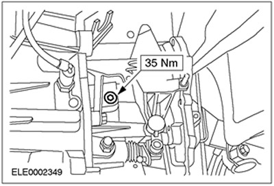
26. Raise the vehicle. Refer to Section 100-02 for additional information.
27. Install the two lower power steering pump bolts and connect the coolant hose.
Cars with air conditioning system
28. Install the air conditioning compressor.
All cars
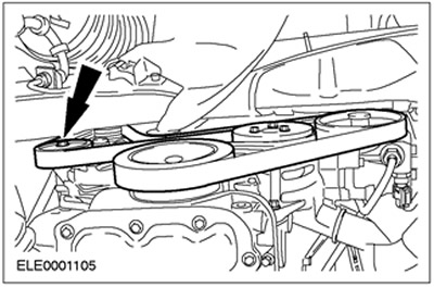
29. Install and tension the drive belt (vehicle without air conditioning shown). Turn the belt tensioner clockwise.
30. Install the drive belt cover.
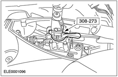
31. Install the shift cable and gear selector cable. Install the shift cable and gear selector cable by turning the support ring located on the bracket clockwise.
32. Fill the transmission fluid to a level of (0-15) mm below the lower edge of the fluid level check hole.
33. Install the shift and selector cable cover.
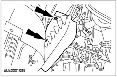
34. Install the air deflector and radiator fan. Align the air deflector and secure it to the top on both sides (left side shown).
35. Lower the vehicle.
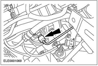
36. Connect the coolant hoses.
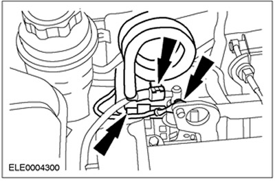
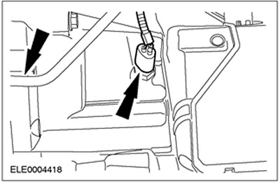
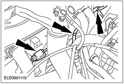
37. Connect the fuel lines. Connect the ground wire.
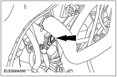
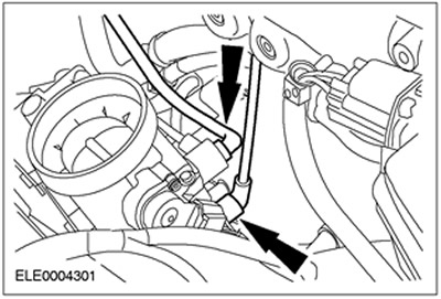
38. Connect the brake booster vacuum hose.
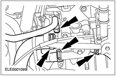
39. Connect the vacuum hoses.
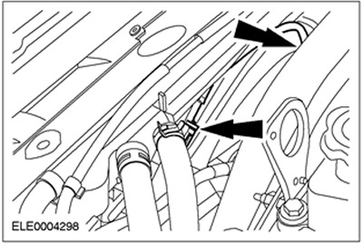
40. Connect the electrical connectors of the reverse light switch and the CKP sensor. Secure the engine wiring harness.
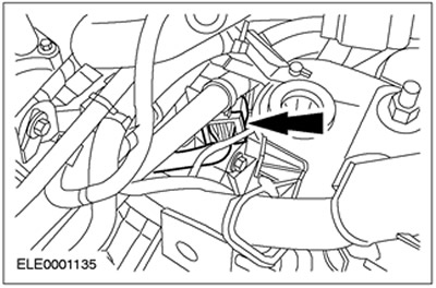
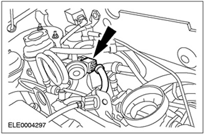
41. Connect the VSS sensor electrical connector.
42. Connect the engine wiring harness electrical connector.
43.
CAUTION: Brake fluid leakage. Follow safe brake fluid handling procedures. Refer to Section 206-00 for additional information.
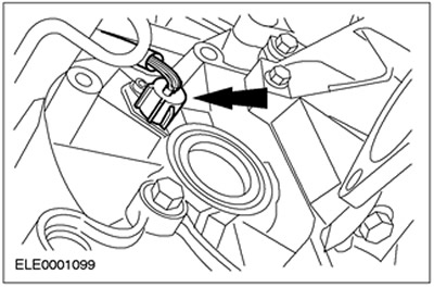
Connect the pressure line to the clutch slave cylinder. Install the spring clamp.
44. Connect the radiator fan electrical connector. Install the clamps.
45. Connect the PCM electrical connector.
46. Connect the heated oxygen sensor (HO2S) connector and the power steering pump pressure switch connector.
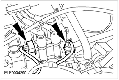
47. Connect the connectors of the EI coil and the radio interference suppression filter.
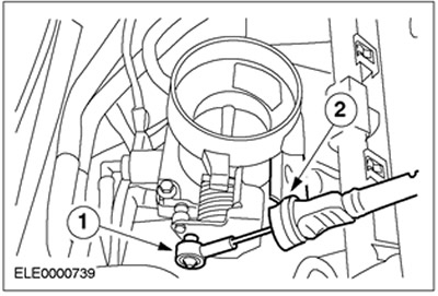
48. Install the accelerator cable.
- 1. Secure the accelerator cable.
- 2. Fix the plastic clamp.
49. Install the intake manifold.
50. Connect the ground cable.
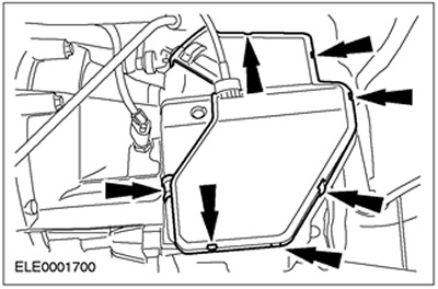
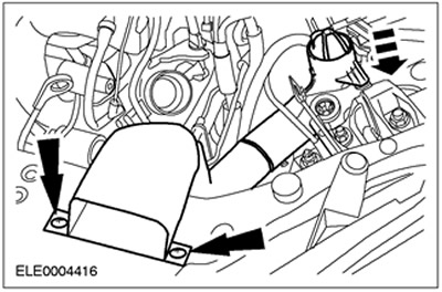
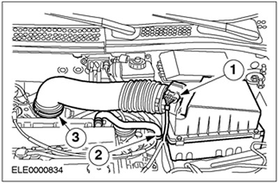
51. Install the air filter housing.
- Install the air filter housing onto the rubber bushing.
- 1. Connect the mass air flow (MAF) sensor connector.
- 2.Connect the crankcase ventilation hose.
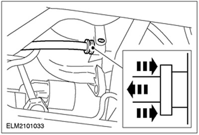
- 3.Connect the inlet hose.
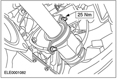
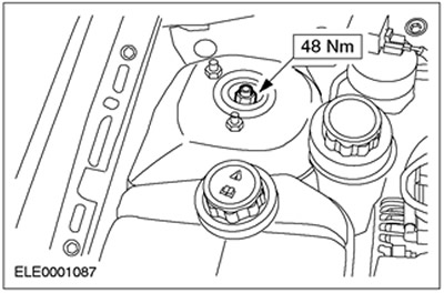
52.
NOTE: Lock against rotation with Allen key.
Tighten the suspension strut nuts on the right and left.
- Tighten by hand using a spanner.
- Use a torque wrench to tighten to the specified torque.
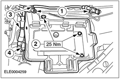
53. Install the battery tray.
- 1. Connect the ground wire and power wire.
- 2. Screw in the bolts.
- 3. Fix the wiring harness in the required position.
- 4. Connect and secure the electrical connector.
54. Install the battery.
55. Remove the special tool. Secure the covers.
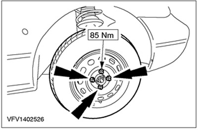
56. Tighten the wheel nuts.
57. Standard finishing operations:
- Fill with coolant. Refer to Section 303-03 for additional information.
- Check the transmission fluid level and add fluid as needed. Refer to Section 308-03A / 308-03B / 308-03C for additional information.
- Bleed the clutch hydraulic system. For additional information, refer to Section 308-03A / 308-03B / 308-03C.
- Enter the radio key code.
- Reprogram preset radio stations.
- Perform a road test to allow the PCM to learn the data.