Special tool
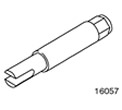 | Front Drive Axle Shaft Puller 308-192 (16-057) |
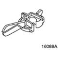 | Gear Shift Lever Neutral Position Adjuster 308-273 (16-088A) |
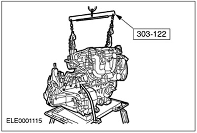
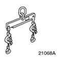 | Engine Lifting Tool 303-122 (21-068A) |
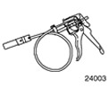 | Radiator Hose Clamp Remover and Installer 303-397 (24-003) |
General equipment:
- Technological plugs
- Assembly table
- Fixing clamp
- Repair zone crane
- Wooden blocks
Removal
All cars
1. General instructions:
- The position of the engine mounts and engine tilt limiters in the description corresponds to the view directed from the gearbox towards the engine.
- If necessary, use special tool 303-397 to remove coolant and ventilation hoses.
- Due to the existence of different variants of the same car model, some working steps are not applicable to all cars. In such cases, this is clearly stated in the text.
- If necessary, remove the clamps and replace them during installation.
2. Standard preparatory activities:
- Please mark the radio key code.
- Mark the preset radio stations.
3.
WARNING: To avoid scalding, cover the filler cap of the expansion tank with a thick cloth before opening the cooling circuit. Failure to follow this instruction may result in injury.
Open the expansion tank of the cooling system.
4.
CAUTION: Disconnect the positive and ground cables from the battery. Remove the battery.
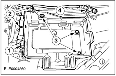
Remove the battery tray and disconnect the ground wire.
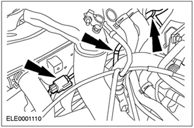
- 1. Release and disconnect the connector.
- 2. Release the wiring harness.
- 3. Unscrew the bolts.
- 4. Disconnect the positive and ground wires.
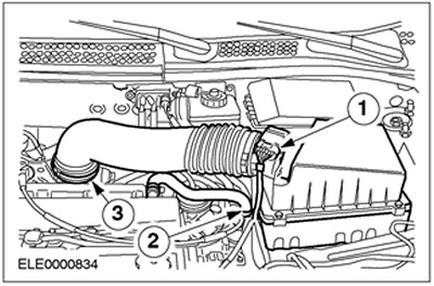
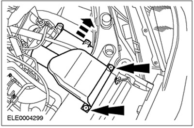
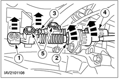
5. Remove the air filter housing.
- 1. Disconnect the mass air flow (MAF) sensor connector.
- 2. Disconnect the PCV hose.
- 3. Disconnect the inlet hose.
- Remove the air filter housing from the rubber bushing.
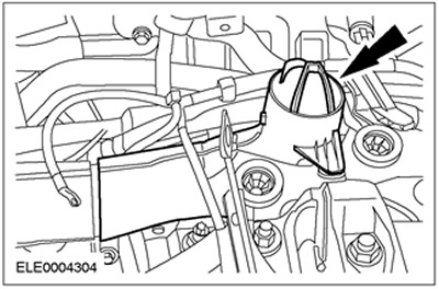
6. Disconnect the ground wire.
7. Remove the intake manifold.
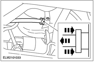
8.
NOTE: The resonator is press-fitted into the bracket.
Remove the air filter inlet pipe together with the resonator.
9.
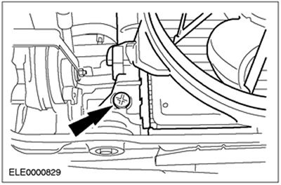
WARNING: Risk of scalding when engine is hot.
Drain the coolant (shown from below). After the coolant has drained, screw the drain plug back in place.
10.
NOTE: Lock against rotation with Allen key.
Loosen the suspension strut nuts on both sides by five turns.
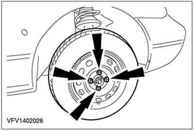
11. Loosen the wheel nuts on the left and right front wheels.
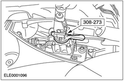
12. Lock the gear shift lever using the special tool.
- Shift the gearshift mechanism to neutral position.
- Remove the gear shift lever cover and insert the special tool.
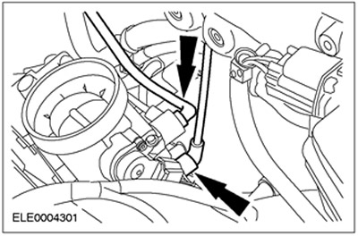
13. Disconnect the accelerator cable.
- 1. Unhook the cable.
- 2.Remove the plastic clamp and set the accelerator cable aside.

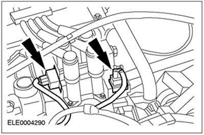
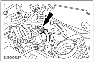
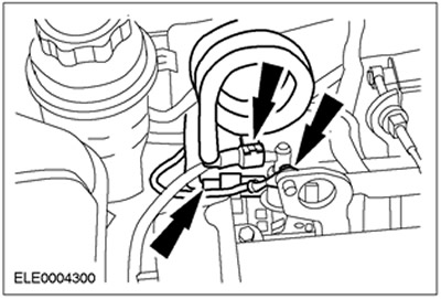
14. Disconnect the connectors of the EI coil and the radio interference suppression filter.
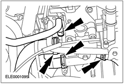
15. Disconnect the heated oxygen sensor (HO2S) connector and the power steering pump pressure switch connector.
16. Disconnect the radiator fan connector. Remove the clamps.
17. Disconnect the powertrain control module (PCM) connector.
18. Disconnect the generator connector.
19.
WARNING: Brake fluid leakage. Avoid contact with skin or eyes. If brake fluid comes into contact with skin or eyes, rinse immediately with water.
CAUTION: If brake fluid comes into contact with the vehicle's paintwork, immediately wash the affected area with water.
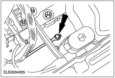
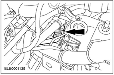
Disconnect the high pressure line from the clutch slave cylinder.
- Release the clamp.
- Disconnect the high pressure line and tie it with clamps.
20. Disconnect the wiring harness connector.
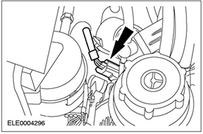
21. Disconnect the vehicle speed sensor (VSS) connector.
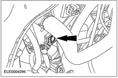
22. Disconnect the plug connector of the reverse light switch and the crankshaft position sensor (CKP). Release the wiring harness from the clamp on the engine.
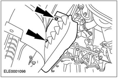
23. Remove the air deflector and radiator fan.
- Release the clamps on both sides (left side shown).
- Unhook the air deflector with an upward movement and remove it with a downward movement.
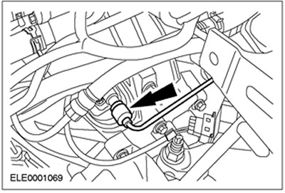
24. Disconnect the low pressure hoses.
25. Disconnect the brake booster vacuum hose.
26. Relieve the fuel pressure. Refer to Subsection 310-00 for additional information.
27.
WARNING: Fuel leakage. Handle fuel with care.
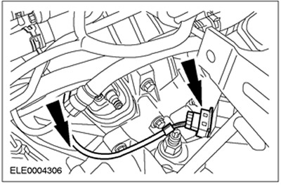
Disconnect the fuel lines. Disconnect the ground wire.
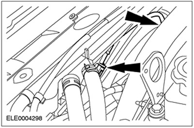
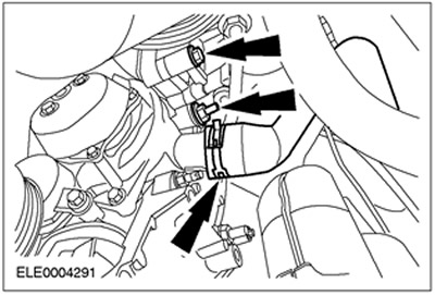
28. Disconnect the coolant hoses.
29. Disconnect the shift cable and gear selector cable from the transmission.
- 1. Disconnect the shift cable from the gear shift lever.
- 2. Release the support rings by turning them counterclockwise and remove the cable assembly from the bracket.
- 3. Disconnect the selector cable from the gear selector lever.
- 4. Release the support rings by turning them counterclockwise and remove the cable assembly from the bracket.
- 5.Release the adjustment mechanism by pressing it.
30. Raise the vehicle. Refer to Subsection 100-02 for additional information.
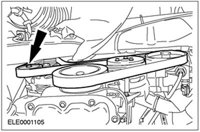
31. Remove the drive belt cover.
32. Loosen the drive belt tension and remove the belt (vehicles without air conditioning). Turn the belt tensioner clockwise.
Cars with air conditioning system
33. Disconnect the air conditioning compressor and tie it to the radiator cross member.
All cars
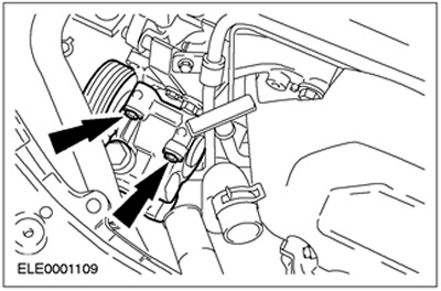
34. Disconnect the coolant hose and remove the power steering pump bolts.
35. Lower the vehicle.
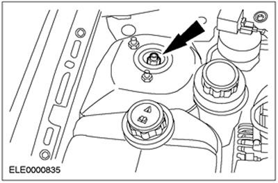
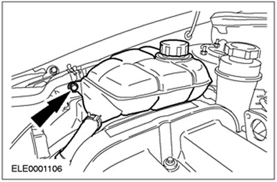
36. Disconnect the expansion tank and set it aside.
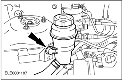
37. Remove the PAS tank and set it aside.
38. Disconnect the power steering high pressure line bracket.
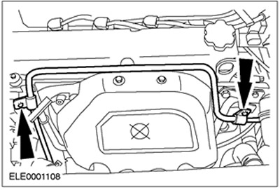
39. Disconnect the power steering pump and tie it with clamps.
40. Raise the vehicle. For additional information, refer to Subsection 100-02.
41. Remove the flexible exhaust pipe.
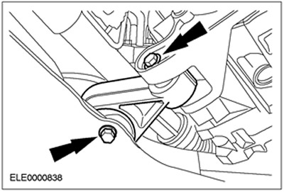
42. Remove the engine roll limiter.
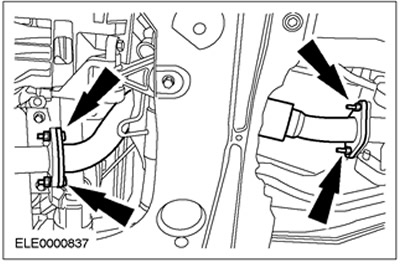
43. Disconnect both suspension arms (right side shown).
44. Remove both front wheels.
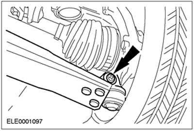
45.
CAUTION: The inner hinge should not be adjusted more than 18 degrees, and the outer hinge should not be adjusted more than 45 degrees.
Disconnect the right half shaft of the front drive axle together with the intermediate shaft.
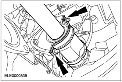
- Remove the intermediate shaft bearing cap.
- Discard the nuts and bearing cap.
- Remove the intermediate shaft with the front drive axle shaft from the gearbox and tie it with clamps.
- Seal the holes in the gearbox with process plugs.
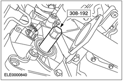
46.
CAUTION: The inner hinge should not be adjusted more than 18 degrees, and the outer hinge should not be adjusted more than 45 degrees.
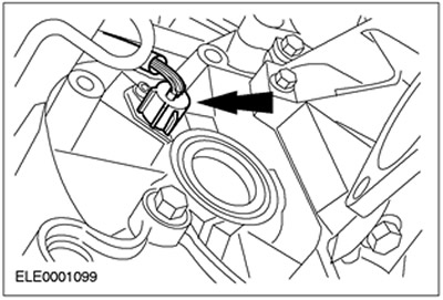
Disconnect the left half shaft of the front drive axle from the gearbox. Use a special tool.
- Remove the front drive axle half shaft and tie it with clamps.
- Seal the holes in the gearbox with process plugs.
47. Place the assembly table with wooden blocks placed on it under the car.
48. Carefully lower the vehicle so that the engine and gearbox assembly remains on the assembly stand.
49. Secure the engine and gearbox assembly to the assembly stand using a retaining clamp.
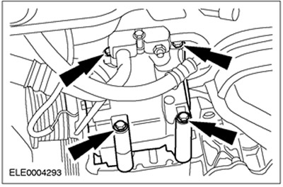
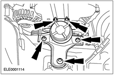
50. Remove the rear engine mount.
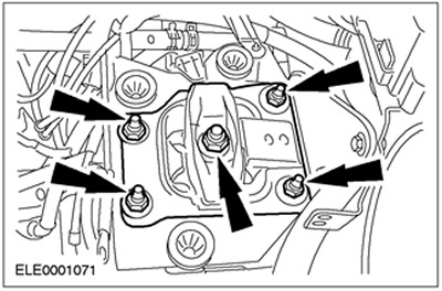
51. Remove the front engine mount.
52. Carefully lift the vehicle. Pull the assembly stand forward together with the engine and gearbox.
53. Attach the engine assembly with the gearbox to the crane.
54. Remove the starter and ground wire.
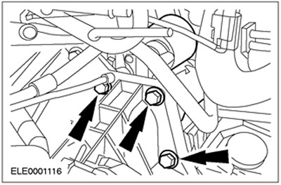
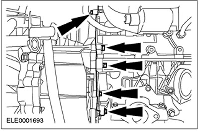
55. Remove the flange bolts.
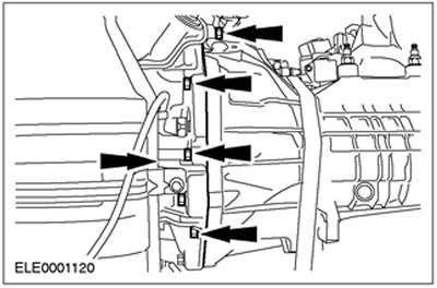
56. Remove the flange bolts (continued).