Special tool
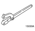 | Universal Flange Holding Wrench 205-072 (15-030 A) |
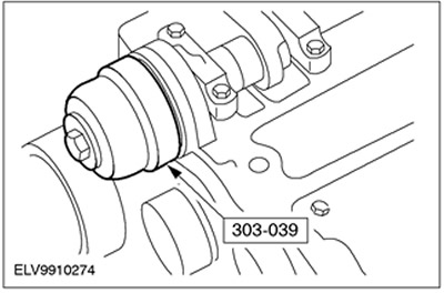
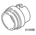 | Oil Seal Replacement Tool 303-039 (21-009 B) |
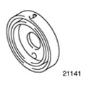 | Oil Seal Replacement Tool 303-291 (21-141) |
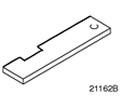 | Camshaft Top Dead Center Setting Tool 303-376 (21-162 B) |
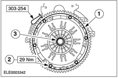
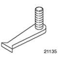 | Flywheel Locking Tool 303-254 (21-135) |
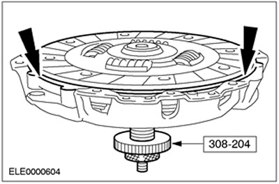
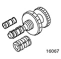 | Clutch Disc Centering Tool 308-204 (16-067) |
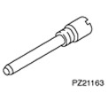 | Crankshaft Top Dead Center Pin 303-620 (21-163) |
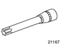 | Cylinder Head Bolt Socket Wrench 303-392 (21-167) |
General equipment:
- Device for compressing piston rings.
- Scraper
- Steel ruler
- Lift
| Name | Specification |
| High temperature grease | ESD-M1C220-A |
| Sealant remover | WSK-M2G348-A4 |
| Sealant for joints between cylinder block and oil pump/oil seal holder | WSK-M4G320-A |
| Sealant for camshaft bearing caps | WSK-M2G348-A5 |
| Oil pan sealant | WSS-M4G323-A7 |
| Motor oil | WSS-M2C912-A1 |
| Silicone grease for spark plug connector seals | A696-M1C171-AA |
1. Preparatory operations:
CAUTION: Do not damage the cylinder liner.
- Remove carbon deposits from the top edge of the cylinder.
- Using a scraper and sealant remover, clean all reusable components and inspect them for damage.
- Clean all threaded holes thoroughly.
2. Available sizes of main bearing shells.
NOTE: Main bearing shells are color coded.
- Size A: (2.145 - 2.152) mm (green color)
- Size B: (2.142 - 2.147) mm (brown color)
- Size C: (2.135 - 2.142) mm (brown color)
- Size D: (2.130 - 2.137) mm (brown color)
3.
NOTE: Use size "B" or "C" main bearing shells (refer to previous item).
Measure the crankshaft radial clearance. For additional information, refer to Section 303-00. Select the bearing shell in accordance with the previous step to provide a clearance of (0.020 - 0.040) mm.
4. Measure the crankshaft end play. Refer to Section 303-00 for additional information.
5. Measure the camshaft radial clearance. Refer to Section 303-00 for additional information.
6. Measure the camshaft end play. Refer to Section 303-00 for additional information.
7. Measure the crankshaft. Refer to Section 303-00 for additional information.
8. Measure the camshaft. Refer to Section 303-00 for additional information.
9. Measure the cylinder diameter. For additional information, refer to Section 303-00.
10. Measure the pistons. Refer to Section 303-00 for additional information.
11. Measure the piston ring joint clearances. Refer to Section 303-00 for additional information.
12. Measure the piston ring end clearances. Refer to Section 303-00 for additional information.
13. Check cylinder head warpage Refer to Section 303-00 for additional information.
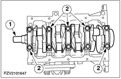
14. Install the crankshaft.
- • Install the main bearing shells into the cylinder block and apply engine oil to them.
- • Apply engine oil to the crankshaft main bearings.
- 1. Install the crankshaft into place.
NOTE: Do not tighten the main bearing cap bolts at this stage.
- 2. Connect the main bearing caps.
15.
NOTE: Connecting rods are numbered starting from the timing belt side. The valve recess in the piston crown faces the exhaust side (1.8L only) and the arrows point toward the timing belt.
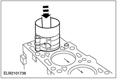
Install the pistons.
- Apply engine oil to the pistons and cylinder liners.
- Distribute the joints of the piston rings and oil scraper ring elements evenly around the circumference (every 120 degrees).
- Compress the piston rings. Use a piston ring compressor.
- Insert the pistons into cylinders No.1 and No.4. Use a hammer handle when installing. The bearing journals of the lower connecting rod heads of cylinders No.1 and No.4 must be in the bottom dead center position.
NOTE: The "Ford" brand designation on the connecting rods faces the timing belt direction.
- Insert clean, oil-free bearing shells into the connecting rod and into the big-end bearing cap.
NOTE: Use new big end bearing cap bolts.
NOTE: Do not tighten the connecting rod cap bolts at this stage.
- Apply engine oil to the connecting rod journals and the lower connecting rod head bearing shells.
- Install the bearing caps.
- Turn the crankshaft 180 degrees and insert pistons #2 and #3.
16.
NOTE: The crankshaft should turn freely. Check and adjust bearing clearances if necessary.
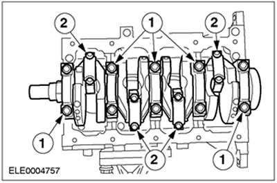
Tighten the main bearings and big end bearings.
- 1. Tighten the main bearing cap bolts to 83 Nm.
- 2. Tighten the connecting rod lower end bearing bolts in two stages.
- 1st stage: 15 Nm
- Stage 2: 90 degrees
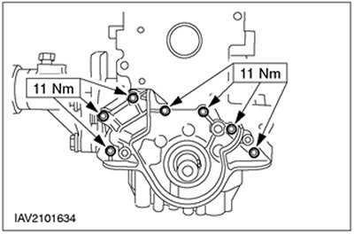
17. Install the rear oil seal holder and the CKP sensor together with the bracket.
- Align the oil seal retainer with the new oil seal and tighten the bolts finger tight.
- 1.Adjust the position of the oil seal holder so that its sealing surface is located (0.3 - 0.8) mm below the cylinder block.
- 2. Tighten the bolts.
- 3. Connect the CKP sensor bracket.
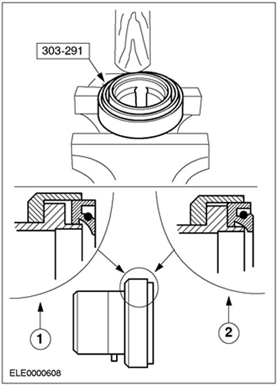
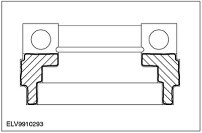
18.
CAUTION: The oil seal must be inserted into special tool 303-291 until it stops.
Insert the new crankshaft rear oil seal into the special tool.
- To ensure proper installation, clamp the special tool in a vice and insert the oil seal using the handle of a hammer during installation.
- 1.Incorrect installation
- 2. Correct installation
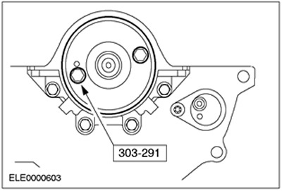
19.
NOTE: Use two flywheel bolts.
Insert the oil seal using the flywheel.
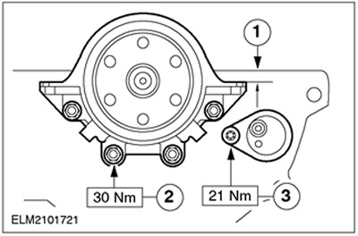
20. Check the position of the oil pump.
- Install the oil pump with a new gasket and tighten the bolts finger tight.
- Align the oil pump on both sides so that the mating surface is (0.3 - 0.8) mm above the lower edge of the cylinder block.
21. Install the oil pump with a new front crankshaft oil seal. Tighten the bolts and check the alignment as described in the previous step. Adjust if necessary.
22.
NOTE: Lower crankcase bolts must be tightened to the specified torque within 10 minutes of applying sealant.
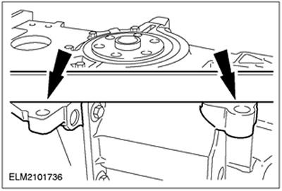
Check the position of the lower section of the crankcase.
- Apply sealant to the joints between the cylinder block and the oil pump/oil pump holder.
- Install the lower crankcase section with a new gasket and tighten the bolts finger tight.
NOTE: If the permissible protrusion and/or clearance values are exceeded, install the adjusting spacers as described in the next paragraph.
- Align the lower crankcase section using a steel straightedge so that the cylinder block and lower crankcase section are flush or at least the offset does not exceed the following values:
- Mechanical gearbox MTX 75: from 0.10 mm protrusion to 0.25 mm gap
- Automatic transmission: from 0.00 to 0.25 mm clearance.
23.
NOTE: From 01.99 only round spacers are used.
If necessary, install lower crankcase spacer washers:
- for a gap of (0.26-0.50) mm, install 0.25 mm spacer washers;
- for a gap of (0.51-0.75) mm, install 0.50 mm spacer washers.
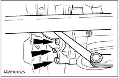
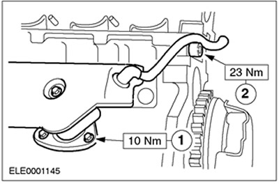
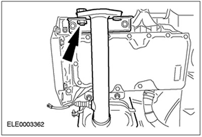
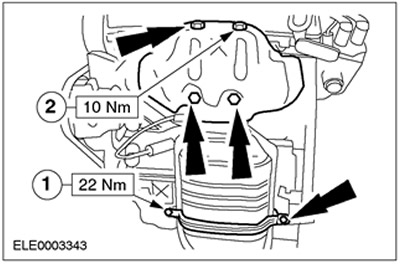
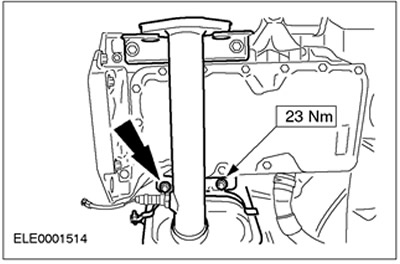
24. Connect the lower crankcase section and the oil inlet pipe together with a new gasket.
- 1. Tighten the bolts and check the alignment as described in the previous paragraph. Adjust if necessary.
- 2. Oil inlet pipe bolts
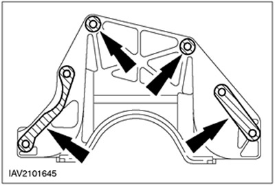
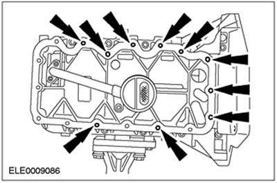
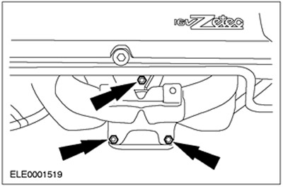
25.
CAUTION: Use studs. If sealant gets into blind holes, damage to the lower crankcase section may occur.
Screw ten studs (M6x20) into the blind holes shown.
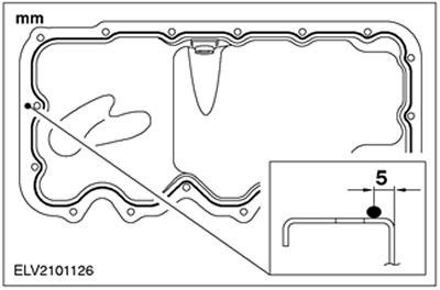
26.
NOTE: Once the oil pan has made contact with the lower crankcase section, it cannot be removed again.
NOTE: Secure the oil pan within 10 minutes after applying the sealant.
Apply a 3mm wide bead of sealant to the mating surface of the oil pan.
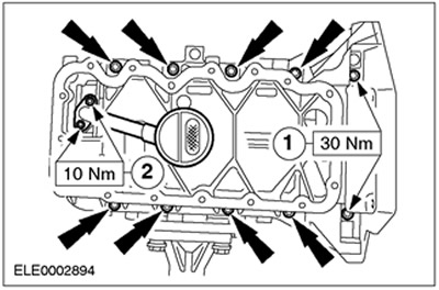
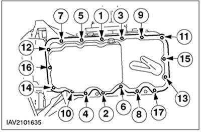
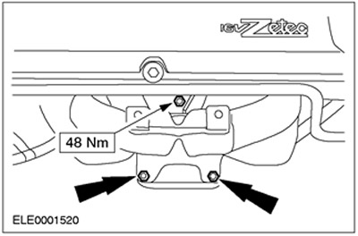
27.
NOTE: Tightening sequence.
Install the oil pan and tighten the bolts, working in two stages.
- 1st stage: 6 N·m
- 2nd stage: 10 N·m
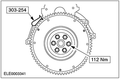
28.
NOTE: Use new bolts.
NOTE: Remove any remaining thread locking compound from the threaded holes.
Install the flywheel. Install the special tool and tighten the bolts.
29.
NOTE: Apply a thin coat of high temperature grease so that when the clutch disc is pushed onto the transmission input shaft, the grease is not squeezed out of the splines.
Apply high-temperature grease evenly over the entire surface of the splines of the driven clutch disc.
30. Center the clutch slave disc on the clutch pressure plate. Use the special tool.
31. Install the clutch.
- 1. Install the clutch pressure plate together with the driven clutch plate centered on it.
- 2. Tighten the bolts in a crisscross pattern in several stages, tightening one turn at a time.
- 3. Check and adjust centering if necessary.
- Detach the special tool.
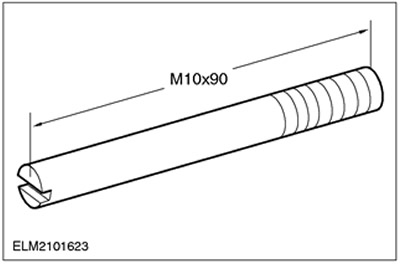
32. Make two guide pins according to the drawing provided.
33.
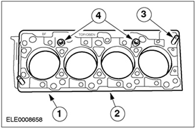
CAUTION: Cylinder head gasket selection depends on the cylinder block casting number (1).
Install a new cylinder head gasket onto the cylinder block.
- 1. Cylinder block numbers.
- 2. Install the new cylinder head gasket in place.
- 3. Screw in the guide pins made in accordance with the description given in the previous paragraph.
- 4. Check that the guide bushings are installed correctly.
34. Install the cylinder head. Secure the cylinder head to the engine lifting eyes on the lift and move it to the required position.
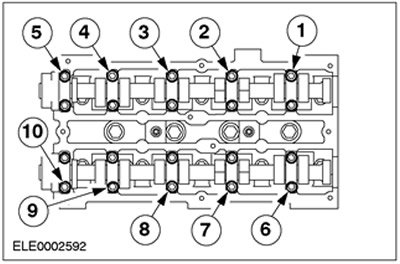
35.
CAUTION: Do not retighten the cylinder head bolts.
NOTE: Install clean (not oily) cylinder head bolts.
NOTE: Tighten the cylinder head bolts using special tool 303-392, working in three stages in the sequence shown.
Install the cylinder head.
- 1st stage: 20 Nm
- 2nd stage: 40 Nm
- Stage 3: 90 degrees
36. Apply engine oil to the valve lifters and install them in the correct sequence.
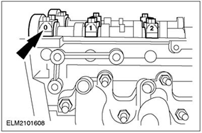
37.
NOTE: Identification numbers are located on the outside of the camshaft bearing caps.
Apply sealant to the marked areas on camshaft bearing caps 0 and 5.
38. Turn the crankshaft to approximately 60 degrees before top dead center.
39.
NOTE: Install the camshafts so that neither cam lobe is in the full lift position.
Apply engine oil to the camshafts and camshaft bearing caps and install them in place.
40.
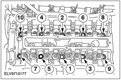
NOTE: Install the camshaft bearing cap bolts, working evenly in several stages, in the sequence shown, turning in 1/2 turn at a time, and then tighten the bolts in two stages.
Tighten the camshaft bearing cap bolts.
- 1st stage: 10 N·m
- 2nd stage: 19 Nm
41. Install the camshaft oil seals.
- Apply engine oil to the camshafts and oil seal lips.
- Install a new oil seal. Use a special tool, washer and bolt M10x70.
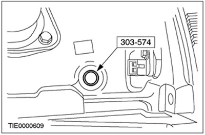
42. Turn the crankshaft to the top dead center position for cylinder No.1.
43.
NOTE: Cylinders #1 and #4 are at top dead center with the woodruff key facing the piston.
Remove the plug and use a special tool to align the crankshaft position at top dead center.
44. Turn the camshafts to the ignition point for cylinder No.1 and insert the special tool into the grooves on the ends of the camshafts.
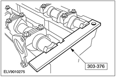
45.
NOTE: Do not tighten the bolts. The camshaft pulleys must turn freely on the camshafts.
Install the pulleys onto the camshafts and tighten the bolts.
46. Insert a new gasket into the water pump.
- 1. Install the gasket in place.
- 2. Fix the gasket by bending the tabs.

CAUTION: Do not twist the timing belt (the bend diameter should be at least 35 mm).
47.
CAUTION: Do not turn the crankshaft. If necessary, check that the crankshaft rests against Special Tool 303-620.
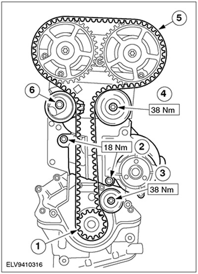
Install a new timing belt.
- 1. Install the crankshaft pulley together with the thrust washer onto the crankshaft.
- 2.Install the water pump.
- 3. Install the lower idler pulley.
- 4. Install the upper idler pulley.
- 5.Reinstall the timing belt, starting at the crankshaft pulley, working counterclockwise and maintaining tension on the belt at all times.
- 6. Install the belt tensioner and tighten the bolts 5 turns.
48.
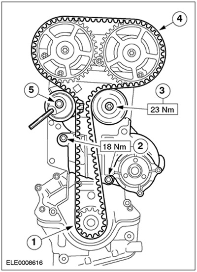
CAUTION: Do not turn the crankshaft. If necessary, check that the crankshaft rests against Special Tool 303-620.
NOTE: Design shown without lower idler pulley (produced from about 01/99 onwards).
NOTE: The tab on the timing belt tensioner should not catch on the metal cover.
Install a new timing belt.
- 1. Install the crankshaft pulley together with the thrust washer onto the crankshaft.
- 2.Install the water pump.
- 3. Install the intermediate pulley.
- 4.Reinstall the timing belt, starting at the crankshaft pulley, working counterclockwise and maintaining tension on the belt at all times.
- 5. Install the belt tensioner and tighten the bolts 5 turns.
49.
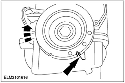
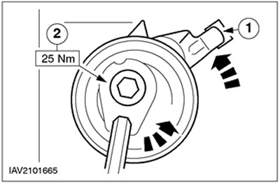
CAUTION: Tighten the timing belt tensioner only by turning it counterclockwise.
NOTE: If the belt tension is not adjusted correctly, this will result in incorrect valve timing.
Tighten the timing belt.
- 1. Attach the belt tensioner to the metal cover.
- 2.Tighten the timing belt by turning the tensioner counterclockwise until the arrow and mark align, then tighten the bolt.
50.
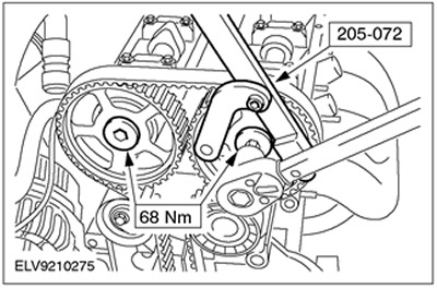
CAUTION: Do not tighten the camshaft pulley bolts while holding the camshafts against rotation with Special Tool 303-376. To prevent rotation, use Special Tool 205-072.
NOTE: The crankshaft must be at TDC position of cylinder No.1.
Tighten the camshaft pulley bolts.
51. Unscrew and remove special tool 303-620.
52. Remove special tool 303-376 from the camshafts.
53.
NOTE: Rotate the engine two revolutions in the direction of normal crankshaft rotation.
Check the valve timing by installing special tools and adjust the alignment if necessary.
- Screw in special tool 303-620 and make sure that the crankshaft rests against the special tool.
- Insert special tool 303-376 into the grooves on the ends of the camshafts. If necessary, release the pulleys and correct the alignment of the camshafts.
- Disconnect the special tools.
54. Install the plug.
55.
CAUTION: To avoid damaging the spark plug connector seal, use a blunt object (such as a plastic tie) to apply silicone grease.
CAUTION: When mating the spark plug connector, keep it in line with the spark plug.
NOTE: Coat the inside of the spark plug connector with silicone grease to a depth of (5-10) mm.
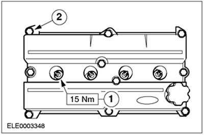
Install the cylinder head cover and spark plugs.
- 1. Screw in the spark plugs.
- 2. Tighten the cylinder head cover bolts in two stages. Stage 1: 2 Nm. Stage 2: 7 Nm
- Connect the spark plug connectors until they snap into place.
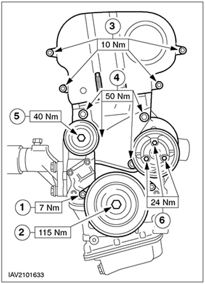
56. Install the timing belt covers and pulleys.
- 1. Bottom cover
- 2.Crankshaft pulley/damper
NOTE: Check the installation of the gasket on the top cover and adjust the gasket position if necessary.
- 3.Top cover
- 4.Center cover/front engine mount bracket
- 5. Intermediate pulley of the drive belt
- 6.Water pump pulley
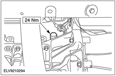
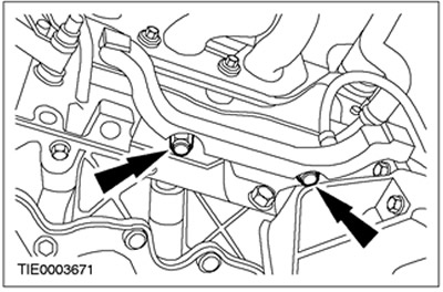
57. Connect the positive crankcase ventilation hose. Use a new seal.
- 1. Three bolts
- 2.One bolt
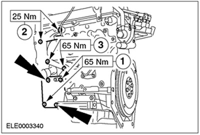
58. Connect the auxiliary elements located on the outlet side.
- 1.Air conditioning compressor bracket
- 2. Bracket for power steering pump, fixed on the cylinder head
- 3. Bracket for the power steering pump fixed to the cylinder block
59. Hook the hoist onto the engine lifting eyes and remove the engine from the assembly stand. Place the engine on the assembly stand and leave it attached to the hoist.
60.
NOTE: Coat the oil filter seal with engine oil.
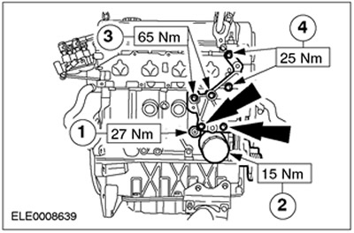
Connect the auxiliary elements located on the inlet side.
- 1. Oil pressure relay
- 2.Install a new oil filter.
- 3. Generator bracket, fixed to the cylinder block
- 4. Generator bracket, fixed to the cylinder head
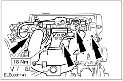
61. Install the intake manifold. Screw in seven bolts and two nuts.
62.
CAUTION: To avoid damaging the catalytic converter, always follow the correct installation procedure.
Loosen the catalytic converter bracket enough to allow it to move freely.
63.
NOTE: Use a new gasket.
NOTE: Do not tighten the nuts/bolts at this stage.
Position the catalytic converter on the exhaust manifold.
64. Using the nut and bolt, temporarily secure the catalytic converter to the bracket located at the rear.
65. Tighten the catalytic converter to exhaust manifold mounting bolts.
66. Secure the catalytic converter.
- 1. Tighten the bolts on the catalytic converter mounting bracket.
- 2. Install the heat shield.
67. Attach the catalytic converter mounting bracket.
- Tighten the bolts.
- Remove the temporary bolt from the rear catalytic converter mounting bracket.
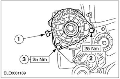
68. Install the generator.
- 1. Screw in and tighten the bolt.
- 2. Tighten the bolt.
- 3.Connect the positive wire.
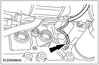
69. Connect the electrical connector of the oil pressure switch.