Disassembly
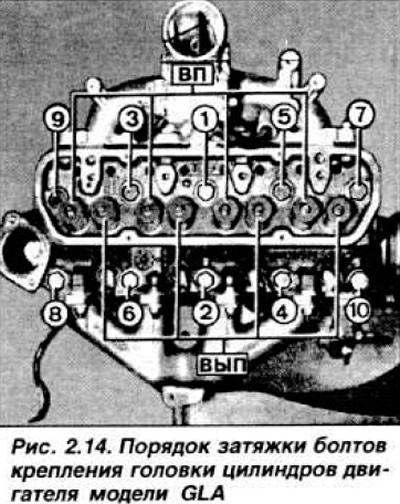
Separate the gearbox from the engine, remove the distribution pipe of the cooling system. Install the engine on the stand. Remove wires from spark plugs. distributor cap, rotor and spark plugs. Remove the oil filler plug with oil recirculation hoses. Remove the thermostat cover and thermostat, having previously marked its position. Remove the cylinder head cover and the rocker shaft. Remove the rocker arms and lay them in order so that they can be installed in their original places during assembly. In reverse order (pic. 2.14), unscrew the cylinder head bolts and remove the cylinder head together with the intake manifold and exhaust manifold.
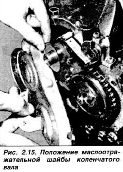
Loosen the ignition distributor mounting bolt and remove it complete with the mounting plate. Remove fuel pump with heat seal. then the oil pump and emergency oil pressure switch Remove the alternator and drive belt. Remove crankshaft pulley and oil pan. If necessary, apply light blows with a mallet to separate it. Remove the timing chain cover, store its fastening bolts separately from other fasteners. Remove the oil slinger from the end of the crankshaft, marking its position (pic. 2.15).
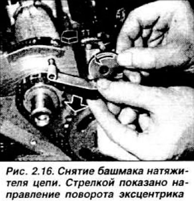
Turn the chain tensioner eccentric by hand and remove the tensioner shoe (pic. 2.16). Loosen the mounting bolts and remove the camshaft sprocket with chain.
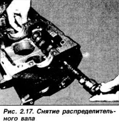
Loosen the camshaft retaining flange bolts and carefully remove the camshaft (pic. 2.17), turning it in order to drown all the pushers.
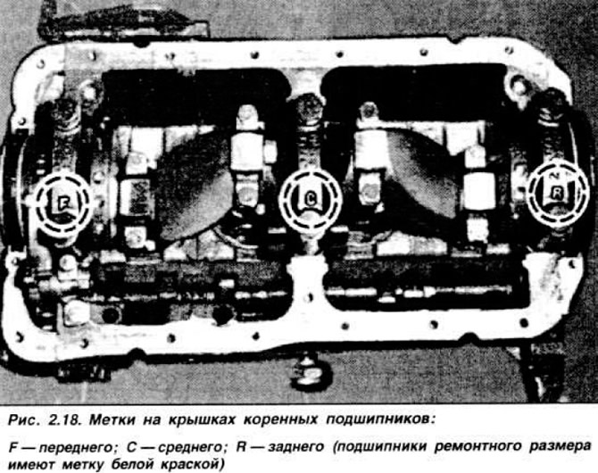
Then remove the tappets and lay them in order Using a universal puller, remove the sprocket from the crankshaft. Check for marks on the main and connecting rod bearing caps (pic. 2.18).
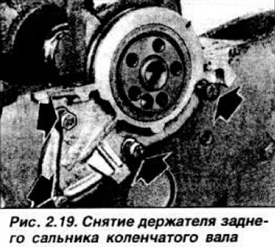
If necessary, apply marks before removing them Remove the connecting rod bearing caps with shells, remove the pistons with connecting rods. Install the caps on the respective connecting rods without tightening the bolts. Remove clutch pressure plate and flywheel. Remove the crankshaft rear oil seal holder (pic. 2.19).
Remove main bearing caps. When removing thrust half rings 9 and 11 (pic. 2.20), if they are to be reused, mark their position with paint.
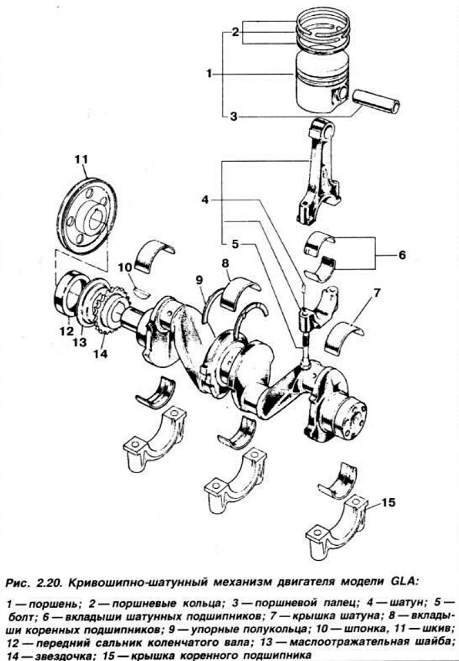
Remove crankshaft. mark the inserts if they are to be used again.
Checking Engine Parts
Rinse all parts and dry them with compressed air. Using an injection syringe, pump trichlorethylene through the lubrication channels of the crankshaft. if necessary, remove deposits with copper wire and blow out the channels. In the same way, clean the oil channels of the cylinder block and wrap or press in new plugs, having previously applied a lot of sealant such as Loctite Frenetanch to them.
Check the technical condition of the washed parts, paying attention to What:
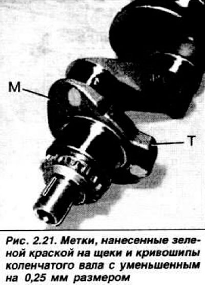
- on the engine installed at the factory. main journals may have a nominal (without labels) or reduced by 0.25 mm size (green bevel points on the crankshaft crank near the undersized journal) (pic. 2.21);
- on a factory installed engine, the crankpins may have a nominal (without labels) or reduced by 0.25 mm size (dots of green paint);
- on a factory-installed engine, the main and connecting rod bearing shells do not have any marks;
- on engines with a rebuilt crankshaft, oversized main bearing shells are marked with paint on the back of the shells;
- on engines repaired by the aggregate replacement method, liners increased by 0.50, 0.75, 1.0 mm in size have marks painted on the edge of the liner with paint.
In any case, it is necessary to measure the size of the connecting rod and main journals and the corresponding liners. The gap between the liners and the necks must be checked with a calibrated plastic wire.
Install the main bearing shells in the cylinder block bed and lay the crankshaft. Wipe the connecting rod (indigenous) neck and matching insert and cap. Put a piece of calibrated wire on the neck, install the cover and tighten with a torque of 8.8-10.2 kgf·m for main bearings or 2.6-3.3 kgf·m for connecting rod bearings. Do not turn the crankshaft. Remove the cover and use the scale on the bag of wire to determine the size of the gap by flattening the wire. Measure the clearances for all main and connecting rod journals. Then, using an inside gauge, measure the ovality and taper of the cylinders. In case of excessive wear, bore out the cylinders.
NOTE: Spare parts come with dry cylinder liners, installation of which should be entrusted to a specialist.
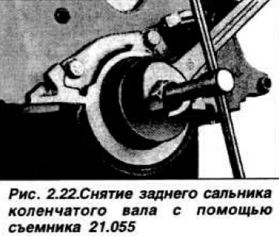
Installing piston rings in series in the cylinders, measure the gap in the lock. Measure the clearance between the ring and the piston groove. Replace front and rear crankshaft oil seals. The rear oil seal is removed using tool 21.055 (pic. 2.22), and for its installation it is necessary to have a piece of pipe of the appropriate diameter or a mandrel 21.059.
Assembly
Install the sprocket onto the crankshaft with the mark on the sprocket facing forward. Using the pulley and its fastening bolt, put the sprocket in place; it is forbidden to hit the sprocket. Lubricate the valve tappets v install in the appropriate seats. Lubricate the bushings and journals of the camshaft with engine oil and carefully, so as not to damage the bushings, insert the camshaft from the front. Fix the locking flange and use the indicator to measure the camshaft end play. If necessary, install a flange of the desired thickness.
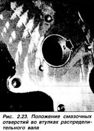
NOTE: When replacing the bushings of the camshaft bearings, pay attention to their correct installation (pic. 2.23).
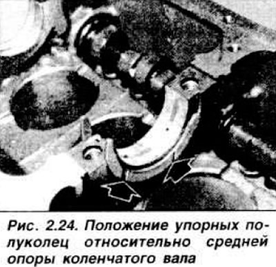
Without lubrication, install the main bearing shells in the bed of the cylinder block and lay the crankshaft on them. Install thrust half rings on both sides of the middle main bearing, anti-friction side with lubrication grooves towards the crankshaft (fig 2.24).
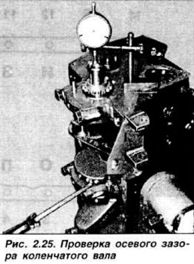
Lubricate the crankshaft main journals with engine oil and install the covers with liners, observing the alignment marks: F - front support. C - middle, R - rear support (flywheel side). The arrows on the covers must point forward. Screw in the bolts for fastening the covers, then tighten them with a torque of 8.8-10.2 kgf·m. Bring the leg of the dial indicator to the end of the crankshaft (fig 2.25) and measure the axial clearance of the crankshaft; if necessary, replace the circlips.
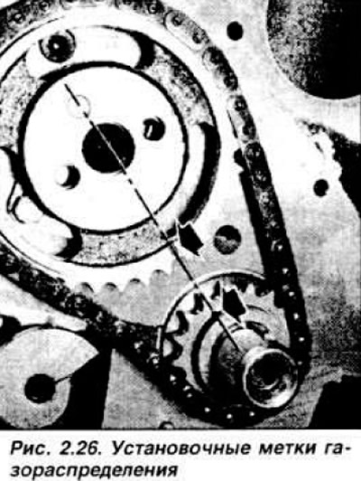
Slide the timing chain onto the camshaft sprocket and install the sprocket onto the camshaft. simultaneously putting the chain on the crankshaft sprocket and paying attention to the position of the marks on both sprockets (pic. 2 26).
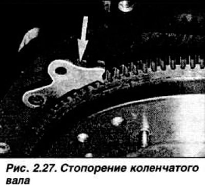
Tighten the camshaft sprocket mounting bolts to a torque of 1.6-2.0 kgf·m and bend the edges of the lock washer to the edge of the bolt head. Rotate the chain tensioner eccentric and install the shoe bracket on the axle. Release the eccentric and make sure it rests on the teeth of the shoe bracket. On the end of the crankshaft, install the oil slinger with the convex side to the timing chain. Install the chain cover with a new gasket. Lubricate with engine oil and install the crankshaft pulley. Install the crankshaft rear oil seal retainer and flywheel. Lock the crankshaft with a screwdriver or a sharpened automatic transmission locking pin (pic. 2.27) and tighten the pulley mounting bolts to a torque of 5.4-5.9 kgf·m.
Install the clutch disc with the protruding part of the hub towards the gearbox, center it using mandrel 21.052 and install the clutch pressure plate, tightening the mounting bolts crosswise in several steps to a torque of 0.7-1.0 kgf·m.
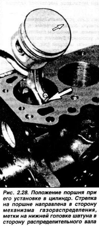
Lubricate with engine oil and dilute the piston rings, lubricate the cylinder mirror and. using a clamp to compress the rings (pic. 2.11), install the pistons with connecting rods in the corresponding cylinders, observing the installation direction: arrow on the piston crown towards the timing mechanism drive (pic. 2.28). the mark on the bottom head of the connecting rod is towards the camshaft.
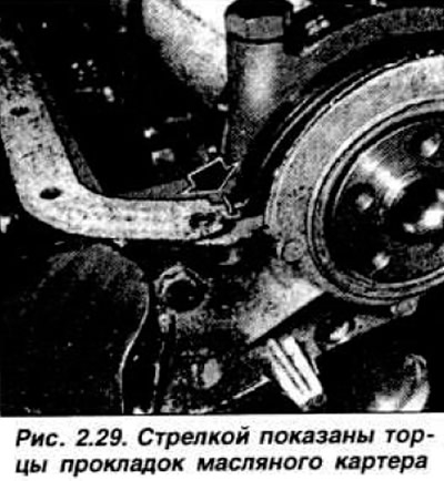
Turn the cylinder block over, lubricate the liners and install the connecting rod bearing caps according to the marks; tighten the bolts to a torque of 2.6-3.3 kgf·m. Install the oil pickup tube. Apply a layer of Perfect Seal to the mating plane of the cylinder block with the oil sump. install neoprene pads on front and rear crankshaft bearings and cork side pads (pic. 2.29), install the oil sump and tighten the mounting bolts in several stages: on a cold engine, in order. in letters, then in numerical order (pic. 2.30).
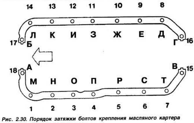
The final tightening should be done on a hot engine with a torque of 0.8-1.1 kgf·m in order. indicated by letters. Turn the crankshaft and set the piston of the first cylinder to the TDC of the compression stroke Install the ignition distributor, while the rotor must be directed perpendicular to the cylinder block Install the cylinder head, fuel pump with a heat insulating gasket, connect the fuel hose to the carburetor fitting. Install the water pump, then its pulley and thermostat, paying attention to its position, install the thermostat cover with gasket. Install the oil pump. Screw in the spark plugs using a 16 mm spark plug wrench and connect the high voltage wires. Install alternator and adjust drive belt tension.
Visitor comments