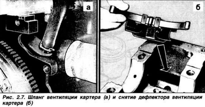
Move the tensioner to the left and remove the toothed belt. Remove high voltage wires. distributor cap and remove the spark plugs. Remove the crankcase ventilation hose from the pipe on the cylinder block (fig 2.7,a).
Remove cylinder head cover. To turn away bolts of fastening in return sequence shown on fig. 2.14. and remove the cylinder head assembly with intake and exhaust manifolds. Remove the head gasket. Remove the engine oil sump. Remove the clutch pressure and driven discs. then the engine flywheel. Remove the crankshaft oil seal and its holder. Remove toothed belt tensioner. Loosen the four mounting bolts and remove the water pump. Press the toothed pulley off the crankshaft using puller 21-098 if necessary. remove the spacer ring. Remove the oil pump seal. Loosen the bolts securing the oil intake tube and the oil pump and remove the oil pump assembly with the oil intake. Remove the emergency oil pressure switch. Set the pistons to an intermediate position between TDC and BDC and remove carbon deposits in the cylinders with a scraper. Check for marks on the main and connecting rod bearing caps (pic. 2.8).
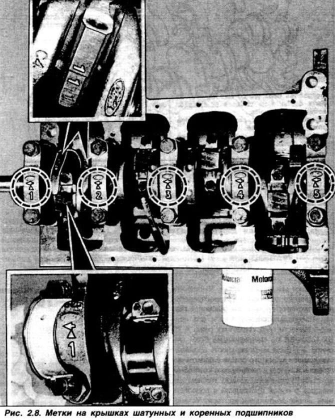
Remove the connecting rod bearing caps with bearing shells. Move the pistons with the connecting rods up, remove the upper connecting rod bearings and lay them in order together with the covers. Remove main bearing caps with bearings. Carefully remove crankshaft. Remove the upper main bearings and thrust half rings and lay the bearings in order together with the covers. Remove deflector (pic. 2.7.6) crankcase ventilation along with a spring. Remove pistons and connecting rods one by one.
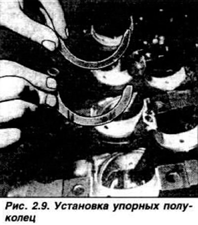
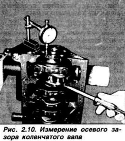
Before assembling the engine, it is necessary to measure the gap in the mates of the main bearing cap with a plastic calibrated wire, lubricating them with engine oil. Tighten the fastening bolts to a torque of 9.0-10.0 kgf·m. The main bearing caps are numbered. When installing, the arrow on the cover must point forward. Use a dial indicator to measure the crankshaft end play (pic. 2.10). adjust if necessary. by installing thrust half rings of appropriate thickness.
Install rings on pistons. The compression rings are molybdenum coated. take care not to damage it during assembly.
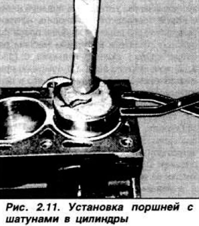
The mark on the second compression ring must point towards the piston pin. The ends of the spring expander of the oil scraper ring must be installed end-to-end, and not overlapped. Open the ring locks by 120°around the circumference. Lubricate pistons with connecting rods and cylinder mirrors with engine oil. Squeezing the rings with a special clamp (pic. 2.11), get the pistons into the cylinders. The arrow on the bottom of the piston and the mark cast near the hole for the finger must be directed towards the drive of the gas distribution mechanism.
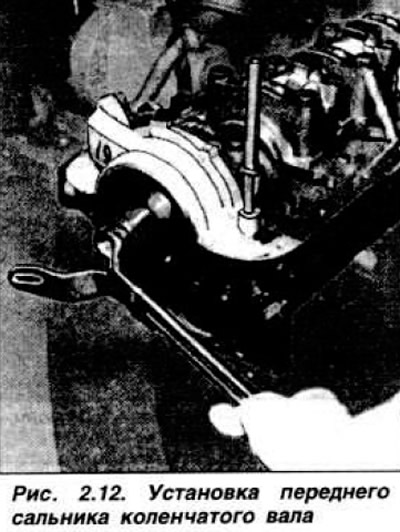
Lubricate the connecting rod bearing shells and install them in the connecting rods and connecting rod caps. Install the connecting rod caps according to the numbers, paying attention to the correct position of the dowel pins. Install the emergency oil pressure switch. Fill with oil and install the oil pump by turning the gears by hand. Install the oil seal using tool 21-093. slightly lubricating the working edges (pic. 2.12) Install the spacer with the convex side outwards, press on the toothed pulley.
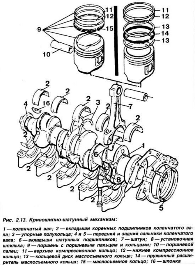
Install water pump with new gasket. Set the toothed belt tensioner to the leftmost position. Lubricate the working lip of the rear oil seal with engine oil 5 (pic. 2.13) crankshaft and using tool 21-095 install it in the holder.
Check the condition of the threads of the flywheel mounting bolts, apply sealant to the threads and install the flywheel. Install the clutch pressure plate assembly with the drive plate on the flywheel, center the driven plate using mandrel 21-052. Install new gaskets on the rear mating surface and in the groove of the oil pump cover. Apply a bead of sealant to the mating surface of the cylinder block with the rear mating surface and with the oil pump cover. Install the toothed belt on the crankshaft pulley, install the gaskets and the oil sump. Ensure that the dowel pins are present and install the cylinder head gasket. Turn the crankshaft and set the piston of the first cylinder 2 cm from TDC. Install the cylinder head and tighten the new bolts in four stages: 1st - 2.5 kgf·m; 2nd — 5.5 kgf·m; 3 - tighten by 90°; 4th - tighten by 90°in the order shown in fig. 2.14.
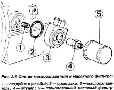
Install the camshaft sprocket, aligning its mark with the mark on the cylinder head, the crankshaft sprocket key with the mark on the oil pump cover. Carry out the timing and toothed belt installation operations as described in chapter «Camshaft and its drive». Apply a layer of sealant (type A 70 SX-19554-BA to Ford specification) 2-3 cm wide on the mating surface of the toothed belt cover with the cylinder block and the cylinder head with the valve cover. Install the cylinder head cover with a new gasket and connect the crankcase breather hose. Install the timing belt cover, then install the crankshaft pulley Screw in the spark plugs, install the distributor cap and high voltage wires Install the oil filter, and on engines with injection, the oil cooler, then the oil drain plug with a new gasket. Install the oil dipstick, connect the heater hose to the water pump. Install generator with bracket (and protective guard on GMA, GPA engines. GLA) and drive belt.
Visitor comments