CVH gasoline engines of car Ford Escort 4

General data of the CVH engine
The CVH engine (C – Compound, V – Valve angle, H – Hemispherical chamber) has a V-shaped arrangement of valves. The camshaft, mounted on five bearings in the cylinder...
The CVH engine (C – Compound, V – Valve angle, H – Hemispherical chamber) has a V-shaped arrangement of valves. The camshaft, mounted on five bearings in the cylinder...
Main parameters of CVH engines
Engine designation 1,1 LC 1,1 HC 1,3 HC 1,4 HC 2V 1,6 HC 2V 1,6EFI 1,6 HC 1,3 HC RS Release period 8/80 –12/85 8/80 –12/85 8/80 –12/85 2/87 1/86 – 9/85 – 8/80 –12/85...
Engine designation 1,1 LC 1,1 HC 1,3 HC 1,4 HC 2V 1,6 HC 2V 1,6EFI 1,6 HC 1,3 HC RS Release period 8/80 –12/85 8/80 –12/85 8/80 –12/85 2/87 1/86 – 9/85 – 8/80 –12/85...
Cylinder Head — Specifications
The cylinder head is made of aluminum alloy with spherical combustion chambers and valves inclined in two planes, controlled by hydraulic tappets through levers from the...
The cylinder head is made of aluminum alloy with spherical combustion chambers and valves inclined in two planes, controlled by hydraulic tappets through levers from the...
Engine Block — Specifications
The engine cylinder block is cast from cast iron. The cylinders are made directly in the cylinder block. Cylinder diameters in engines with a working volume of 1.1 dm³,...
The engine cylinder block is cast from cast iron. The cylinders are made directly in the cylinder block. Cylinder diameters in engines with a working volume of 1.1 dm³,...
Crank mechanism — specifications
Crankshaft The steel crankshaft is supported by five bearings. Axial play 0.09 – 0.30 mm Main journal diameters: – nominal size 57,980 – 58,000 mm – repair size -0.25...
Crankshaft The steel crankshaft is supported by five bearings. Axial play 0.09 – 0.30 mm Main journal diameters: – nominal size 57,980 – 58,000 mm – repair size -0.25...
Valve timing system — specifications
The camshaft is located in the cylinder head, drives the valves via a valve lever and is driven by a toothed belt. The valve clearance is set automatically. Distribution...
The camshaft is located in the cylinder head, drives the valves via a valve lever and is driven by a toothed belt. The valve clearance is set automatically. Distribution...
Fuel System — Specifications
Fuel tank Made of stamped sheet metal and installed in front of the rear axle of the car. Tank capacity: 40 l. Fuel pump The mechanical diaphragm pump is driven by the...
Fuel tank Made of stamped sheet metal and installed in front of the rear axle of the car. Tank capacity: 40 l. Fuel pump The mechanical diaphragm pump is driven by the...
Contact ignition system — specifications
The Bosch or Lucas contact ignition system consists of a battery, ignition coil, distributor with breaker and spark plugs. The firing order is 1–3–4–2. Distributor Brand...
The Bosch or Lucas contact ignition system consists of a battery, ignition coil, distributor with breaker and spark plugs. The firing order is 1–3–4–2. Distributor Brand...

Contactless Ignition System — Specifications
Spark advance characteristics of the Lucas ignition distributor for the 1.3 dm³ engine A - centrifugal regulator; B – vacuum regulator Characteristics of ignition timing...
Spark advance characteristics of the Lucas ignition distributor for the 1.3 dm³ engine A - centrifugal regulator; B – vacuum regulator Characteristics of ignition timing...
Lubrication system — specifications
Oil pump The gear oil pump with built-in pressure reducing valve is installed in the front part of the engine cylinder block and is driven by the engine crankshaft. Oil...
Oil pump The gear oil pump with built-in pressure reducing valve is installed in the front part of the engine cylinder block and is driven by the engine crankshaft. Oil...
Cooling system — specifications
Coolant Coolant replacement: once every two years. The ratio of Ford concentrate and water for the preparation of a coolant operating at temperatures down to minus 30°C...
Coolant Coolant replacement: once every two years. The ratio of Ford concentrate and water for the preparation of a coolant operating at temperatures down to minus 30°C...
Tightening torques for threaded connections
Cylinder head bolts: - Stage 1 22 – 25 Nm - 2nd stage 50 – 60 Nm - Stage 3 turn 90° - Stage 4 turn 90° Camshaft retaining plate bolts 10 – 15 Nm Main bearing cap bolts...
Cylinder head bolts: - Stage 1 22 – 25 Nm - 2nd stage 50 – 60 Nm - Stage 3 turn 90° - Stage 4 turn 90° Camshaft retaining plate bolts 10 – 15 Nm Main bearing cap bolts...

General view of the CVH engine and engine compartment
Engine bay with 1.6i engine 1 – right pillar; 2 – battery; 3 – oil level gauge; 4 – hose; 5 – inlet pipe; 6 – heater air intake; 7 – injection guide; 8 – accelerator...
Engine bay with 1.6i engine 1 – right pillar; 2 – battery; 3 – oil level gauge; 4 – hose; 5 – inlet pipe; 6 – heater air intake; 7 – injection guide; 8 – accelerator...

Replacing the timing belt
Timing drive 1 – tension roller; 2 – lid; 3 – spring; 4 – pulley; 5 – toothed belt; 6, 8 – key; 7 – water pump pulley; 9 – guide flange; 10 – crankshaft pulley; 11 –...
Timing drive 1 – tension roller; 2 – lid; 3 – spring; 4 – pulley; 5 – toothed belt; 6, 8 – key; 7 – water pump pulley; 9 – guide flange; 10 – crankshaft pulley; 11 –...
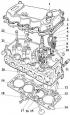
Removing the cylinder head
Cylinder head 1 – oil filler plug; 2 – cylinder head cover; 3 – gasket; 4 – guide plate; 5 – lever; 6 – cracker; 7 – top plate; 8 – spring; 9 – oil deflector cap; 10 –...
Cylinder head 1 – oil filler plug; 2 – cylinder head cover; 3 – gasket; 4 – guide plate; 5 – lever; 6 – cracker; 7 – top plate; 8 – spring; 9 – oil deflector cap; 10 –...

Disassembling the cylinder head
Valve drive mechanism 1. Place the cylinder head in the front and rear parts on two wooden blocks. 2. Remove the manifolds together with the gaskets. 3. Remove the...
Valve drive mechanism 1. Place the cylinder head in the front and rear parts on two wooden blocks. 2. Remove the manifolds together with the gaskets. 3. Remove the...

Checking and repairing the cylinder head
1. Clean and thoroughly blow out all parts with compressed air. Caution! Do not use tools that may scratch the parts being cleaned. 2. To replace the valve lever stud,...
1. Clean and thoroughly blow out all parts with compressed air. Caution! Do not use tools that may scratch the parts being cleaned. 2. To replace the valve lever stud,...

Hydraulic valve lifters
The working principle of a hydraulic tappet Hydraulic valve lifter parts 1 – retaining ring; 2 – plunger; 3 – cylinder; 4 – check valve; 5 – spring; 6 – body The use of...
The working principle of a hydraulic tappet Hydraulic valve lifter parts 1 – retaining ring; 2 – plunger; 3 – cylinder; 4 – check valve; 5 – spring; 6 – body The use of...

Cylinder head assembly
1. Lubricate the valve stem with oil (preferably SAE 90 SQM 2C-9002-AA) and install the valve into the cylinder head. 2. Install the oil deflector cap on the valve stem....
1. Lubricate the valve stem with oil (preferably SAE 90 SQM 2C-9002-AA) and install the valve into the cylinder head. 2. Install the oil deflector cap on the valve stem....

Installing the cylinder head
1. Check the presence and reliability of the fastening of the guide bushings A on the engine cylinder block. 2. Turn the crankshaft to a position where all pistons are...
1. Check the presence and reliability of the fastening of the guide bushings A on the engine cylinder block. 2. Turn the crankshaft to a position where all pistons are...
Replacing the camshaft sealing ring
1. Remove the timing belt from the camshaft pulley. 2. Unscrew and remove the toothed pulley from the camshaft, holding the pulley from turning with a rod or...
1. Remove the timing belt from the camshaft pulley. 2. Unscrew and remove the toothed pulley from the camshaft, holding the pulley from turning with a rod or...
Replacing the front crankshaft seal ring
1. Remove the ground wire from the battery. 2. Loosen the lower mounting bolts, unscrew the upper generator tension bolt, tilt the generator toward the engine and remove...
1. Remove the ground wire from the battery. 2. Loosen the lower mounting bolts, unscrew the upper generator tension bolt, tilt the generator toward the engine and remove...

Replacing the oil pan
Elements of the engine lubrication system 1 – oil pump; 2 – gasket; 3 – oil indicator tube; 4 – oil pressure sensor; 5 – oil filter; 6 – oil gauge with indicator; 7 –...
Elements of the engine lubrication system 1 – oil pump; 2 – gasket; 3 – oil indicator tube; 4 – oil pressure sensor; 5 – oil filter; 6 – oil gauge with indicator; 7 –...

Pistons and connecting rods — removal, inspection and installation
Relative position of piston ring locks Removal 1. Remove the cylinder head and oil pan. 2. Check the numbers on the connecting rod caps and connecting rods, as well as...
Relative position of piston ring locks Removal 1. Remove the cylinder head and oil pan. 2. Check the numbers on the connecting rod caps and connecting rods, as well as...

Removing the engine
Thermostat housing and thermostat 1 – gasket; 2 – retaining ring; 3 – thermostat; 4 – rubber ring; 5 – thermostat housing, 6 – plug; 7 – washer; 8 – temperature sensor...
Thermostat housing and thermostat 1 – gasket; 2 – retaining ring; 3 – thermostat; 4 – rubber ring; 5 – thermostat housing, 6 – plug; 7 – washer; 8 – temperature sensor...

Disassembling the engine
Water pump 1 – water pump pulley; 2 – body; 3 – gasket; 4 – pump shaft; 5 – seal; 6 – impeller Oil pump 1 – external gear; 2 – dividing partition; 3 – internal gear...
Water pump 1 – water pump pulley; 2 – body; 3 – gasket; 4 – pump shaft; 5 – seal; 6 – impeller Oil pump 1 – external gear; 2 – dividing partition; 3 – internal gear...
Engine repair
1. Check the ovality, taper and size of the main and connecting rod journals of the crankshaft. 2. When the crankshaft journals are reduced by 0.25 mm, a green mark is...
1. Check the ovality, taper and size of the main and connecting rod journals of the crankshaft. 2. When the crankshaft journals are reduced by 0.25 mm, a green mark is...
Engine assembly
1. Install the oil separator of the engine crankcase ventilation system, checking the accuracy of the location of the spring levers. 2. Install and secure the main...
1. Install the oil separator of the engine crankcase ventilation system, checking the accuracy of the location of the spring levers. 2. Install and secure the main...

Engine installation
1. Apply a thin layer of grease to the splines of the gearbox input shaft and the release bearing guide sleeve. 2. Place the gasket on the guide pins (indicated by...
1. Apply a thin layer of grease to the splines of the gearbox input shaft and the release bearing guide sleeve. 2. Place the gasket on the guide pins (indicated by...
Checking the compression in the cylinders
The compression value shows, in most cases, how worn the cylinder-piston group of the engine is. To measure compression, you need a compression gauge with a maximum...
The compression value shows, in most cases, how worn the cylinder-piston group of the engine is. To measure compression, you need a compression gauge with a maximum...
This section is available on russian, bulgarian, belarusian, ukrainian, serbian, croatian, romanian, polish, slovak, hungarian
Escort 5
Escort 4
Escort 3
- General information
- User manual
- Maintenance
- Engine
- HCS and Endura-E engines
- CVH and PTE engines
- Zetec and Zetec-E engines
- Gasoline engines
- Diesel engines
- Diesel engines (since 1992)
- Cooling and heating
- Carburetors
- CFI fuel injection
- EFI fuel injection
- SEFI fuel injection
- Exhaust system
- Charging and starting system
- Ignition system
- Transmission
- Clutch
- Mechanical gearbox
- Automatic gearbox
- Drive shafts
- Chassis
- Brake system
- Car suspension
- Steering
- Body
- Electrical equipment
- Light and appliances
- Schematic diagrams
Escort 4
- General information
- User manual
- Maintenance
- Gasoline engines
- OHV engine repair
- CVH engine repair
- Fuel system
- Weber 2V carburetor
- KE-Jetronic injection system
- CFI injection system
- Ignition system
- Diesel engines
- Engine repair
- Fuel system
- High pressure pump
- Cooling and lubrication system
- Transmission
- Clutch
- Mechanical gearbox
- Automatic gearbox
- Drive shafts
- Chassis
- Suspension and wheels
- Steering
- Brake system
- Body
- Body elements
- Doors, locks and windows
- Electrical equipment
- Equipment and devices
- Lighting system
- Electrical circuits
Escort 3
- General information
- Maintenance
- Characteristics
- Engine
- Disassembly and assembly
- Cooling system
- Lubrication system
- Supply system
- Fuel injection «K-Jetronic»
- Transmission
- Clutch
- Mechanical gearbox
- Hydromechanical box
- Drive shafts
- Chassis
- Front suspension
- Rear suspension
- Steering
- Brake system
- Electrical equipment
- Starting and charging system
- Ignition system
- Ignition «Escort RS 1600»
- Light and appliances
- Schematic diagrams