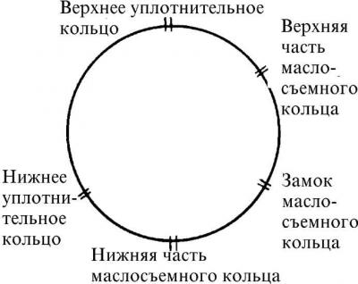
Relative position of piston ring locks
Removal
1. Remove the cylinder head and oil pan.
2. Check the numbers on the connecting rod caps and connecting rods, as well as their position. Connecting rod #1 is located on the timing drive side.
3. If there is carbon deposits on the top of the cylinder, remove them using a soft scraper.
4. Turn the crankshaft by the pulley mounting bolt until the piston of the first cylinder is in the BDC position. Unscrew the connecting rod cover and remove it together with the connecting rod bearing.
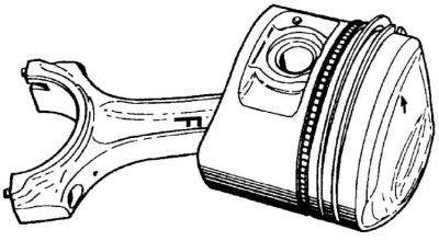
5. Remove the piston with the connecting rod upwards.
6. Remove the remaining pistons in the same manner.
Checking and repair
1. Remove the upper sealing ring, the middle sealing ring and the oil scraper ring one by one. To remove the rings, insert thin steel plates (feelers are also possible) under the ring in several places evenly around the piston perimeter and slide the piston ring off the piston using the plates.
2. Check the ring lock clearance. To do this, insert all rings sequentially from the top into the cylinder working sleeve. Push the ring down into the cylinder with the piston upside down to a depth of 15 mm and measure the ring lock clearance with a feeler gauge. The ring lock clearances are not adjustable, and if the clearance increases beyond the permissible limit, the ring must be replaced.
3. To determine the piston clearance in the cylinders, measure the cylinder diameter. The cylinders are measured in the longitudinal and transverse directions at three levels along the cylinder height. Then subtract the piston diameters from the cylinder diameters, which will give the piston clearance in the cylinder. If the clearance is outside the permissible limits, new sets of pistons and cylinder liners should be installed.
4. Install the piston rings on the piston. The surface of the upper sealing rings is covered with a thin layer of molybdenum, so in order not to damage this layer, it is necessary to be careful when installing the rings on the piston. The oil scraper ring is installed so that the manufacturer's mark is directed toward the piston head or the groove is directed toward the piston pin.
5. Check the clearance in the groove between the piston and the piston ring, lubricate the rings with oil and turn them on the piston to obtain the correct mutual arrangement of the locks (see Fig. Relative position of piston ring locks).
Installation
Caution! Always replace the four pistons together with the pins. If one cylinder needs to be ground, all pistons together with the pins should be ground and replaced. The same diameter also means that they have the same weight, which in turn is a condition for proper engine balancing.
1. Compress the piston rings with a mandrel.
2. Insert the piston with the connecting rod into the cylinder, making sure that the arrow on the bottom of the piston points towards the valve timing drive.
3. Install the connecting rod cap and tighten the bolts to the specified torque.
4. Install the oil pan and cylinder head.
5. Fill the engine with engine oil and coolant into the cooling system.