Note: Conrod bearings 1 to 4 on May 1998 engines are marked on the timing side. On these engines, the connecting rods and connecting rod bearing caps are not interchangeable, as each bearing cap only fits a specific connecting rod. The instructions for marking bearing caps and connecting rods can be ignored if the engine was made after the mentioned date.
Install in the following order:
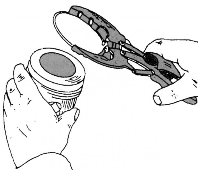
Pic. 76. Removing or installing piston rings with pliers
- Establish piston rings on the piston, as it is shown in fig. 76. If you do not have tongs, pick up three thin metal strips and set the rings (pic. 82);

Pic. 82. Removal and installation of piston rings using metal plates
- distribute the metal strips at regular intervals around the circumference of the piston and put the bottom ring on the strips. One strip should be exactly under the lock of the ring so that there are no scratches;
- advance the piston ring carefully down until it is at the same height as its groove, and remove the metal strips so that the ring fits into the groove;
- Install the second and third ring in the same way on the piston;
- you can also carefully put the rings on with your hands without tools, but at the same time both ends of the ring must be closed, as they can scratch the piston. It must be taken into account that piston rings break very easily if pliers are not used;
- Lubricate the piston rings with engine oil and turn them to the positions indicated above;
- Insert the piston and connecting rod from above into the cylinder block. The arrow on the piston pin must point towards the front of the engine;
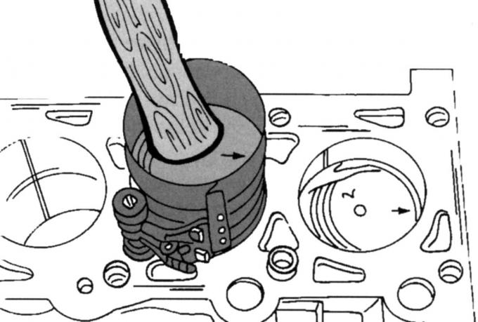
Pic. 83. Installation of pistons
- Compress piston rings a suitable tape collar, as shown in fig. 83. If not available, a very wide hose clamp can be used. Lubricate the piston and bore well with engine oil before installation;
- Turn the crankshaft so that the first and fourth connecting rod journals of the crankshaft are at BDC;
- Insert the bushing into the lower head of the connecting rod and carefully slide the piston with the connecting rod while guiding the connecting rod bearing onto the crankshaft crankpin. Check again that the inscription «Front» pointed towards the front of the engine. From the crankcase side, check if the connecting rod markings are on one side of the engine (how they were marked during engine disassembly). While the piston rings will slip into the cylinder, the tie band will slide out of them, then it can be removed;
Note: On 1.8L exhaust engines from May 1998, the recess in the piston crowns must be on the intake side.
- Establish a cover of the bearing of a rod with the inserted loose leaf. At the same time, make sure that the covers are installed on the connecting rod belonging to them. Check if the numbers on the caps are on the same side as the numbers on the connecting rods. In addition, the trademark (may not be on all engines) must be on the gas distribution side. Insert both guide pins into the bottom end of the connecting rod (if available) in engagement with the connecting rod bearing cover;
- Tighten the connecting rod bearing cap. Tighten both screws first (always use new screws) starting torque and from this position, tighten them a quarter of a turn. See appendix for tightening torques. Turn the crankshaft several times and return the first piston back to BDC. Install the second piston with the crankshaft journal at BDC;
- Turn the crankshaft until the connecting rod journals of the crankshaft of the second and third cylinders are at BDC, and install both pistons and connecting rods in the manner described above.
After installation, check the following again:
- all arrows on the pistons must point towards the front of the engine (on a 1.8L engine from May 1998, also check the notches in the piston crowns);
- the numbering of the connecting rods for the cylinders must be on the same side, the numbers of the connecting rod and the connecting rod bearing cap are the same;
- each connecting rod on the connecting rod journal of the crankshaft should have a small side clearance if the connecting rod bearing is slightly moved in different directions in the axial direction.
Carry out all further work in the same way as when installing the crankshaft.
Visitor comments