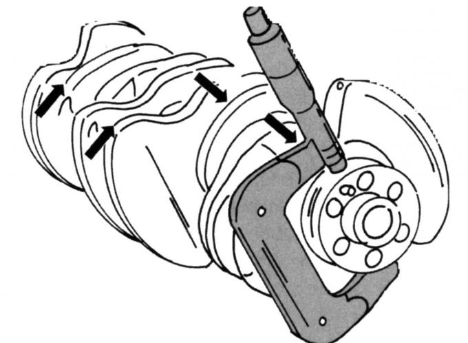
Pic. 84. Measurement of the diameter of the journals of the main bearing
The main bearings of the crankshaft are ground to the nominal size or have a size less than the nominal size by 0.25 mm. To ensure that the correct bearing shells are installed in the engine, it is necessary to measure the crankcase bore and the diameters of each crankshaft main journal. At the same time, make sure that the cheeks of the micrometer do not overlap with the places of the lubrication channels. Each root neck is measured as shown in fig. 84, once in the indicated direction and again after moving the cheeks of the micrometer a quarter of a turn.
Definition of backlash
When installing new bearing shells, it is important to determine the play of the respective bearing. To do this, use the rod «Plastigage» Perfect Circle.
When checking the backlash, do the following:
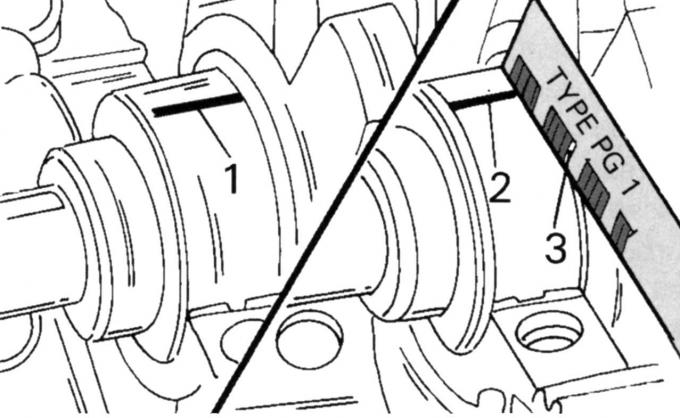
Pic. 85. Measurement of the backlash of the main bearing of the crankshaft: 1 - the original strip; 2 - strip after tightening; 3 - caliber
- put a piece of rod 1 (pic. 85) across the width of the bearing on a clean and dry main journal, then install the main bearing or connecting rod bearing shell with cover from above. Tighten the cover screws to the required torque;
- play in the bearing cannot be measured simultaneously, but only sequentially, bearing by bearing. During the measurement, you can not turn the shaft and hit the bearing caps in order to firmly seat them;
- depending on the available play in the bearing, the plastic rod will flatten. Unscrew the bearing cap. The widely flattened plastic rod 2 sticks either to the main journal or to the liner. Measure the width of the flat plastic rod with the 3 gauge supplied in the Plastigage kit and consider the smallest bearing clearance at the widest point of the strip;
- if one end of the flattened Plastigage rod is wider than the other, there is a difference in bearing clearance. She points to a taper. To measure out-of-roundness, a plastic rod is applied along the entire length of the lower bearing shell (transversely). After tightening to the required torque, the flattened wire is measured. The difference between the largest value and the smallest value determines the roundness deviation.
Note: Connecting rod bearing play has been changed on some engines from May 1998.
Please see the appendix for the relevant data.
Installing the crankshaft
The installation of the crankshaft is carried out in the following order:
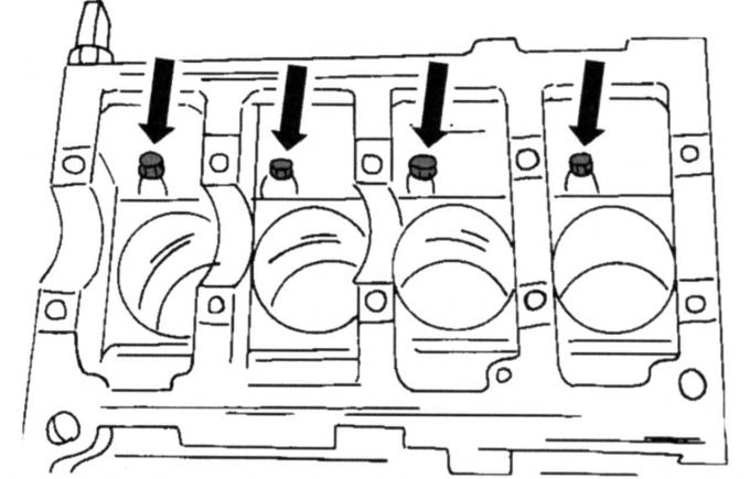
Pic. 86. The location of the four oil nozzles on the inside of the cylinder block
- replace with new oil nozzles for cooling the piston, if they were removed. They are located in the places shown in Fig. 86, and are tightened with a torque of 10 Nm;
- wipe dry the reverse sides of the bearing shells and insert into the hole in such a way that the protrusions of the shells fall into the recesses of the holes. If the same liners are reused, they must be inserted into the appropriate holes. Thrust half rings are located in bearing No. 3 and serve to compensate for axial play;
- Carefully place the crankshaft;
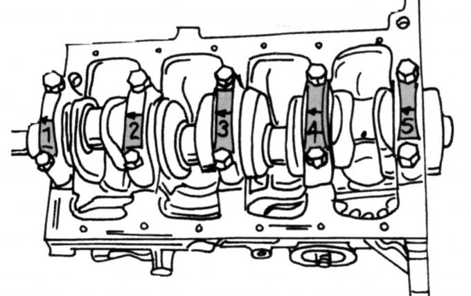
Pic. 87. Numbering of crankshaft main bearing caps
- insert the shells into the main bearing caps (again pay attention to the ledges) and screw the covers in accordance with the markings on the crankcase. Caps are numbered from 1 to 5 (pic. 87). Cover #1 is on the front (gas distribution side). Bearing caps are fastened with screws and studs. Studs refer to bearings 2 and 4;
- evenly tighten the screws securing the bearing caps/nuts, starting from the middle towards both outer sides, in several stages to a final torque of 80 Nm if the engine was manufactured before May 1998. Then tighten the screws with a torque of 83 Nm. Turn the crankshaft several times to determine if it is jammed;
- measure the axial play of the crankshaft, as described in subsection. 2.8.4;
- press the centering bearings of the input shaft of the gearbox into the rear end of the crankshaft;
- Install the pistons and connecting rods, as described in subsection. 2.6.4;
- Screw in the oil pressure switch;
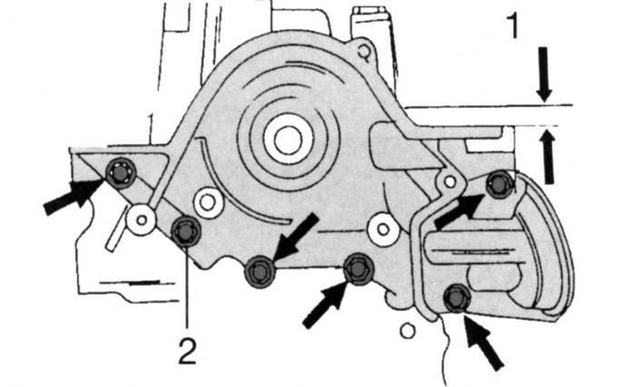
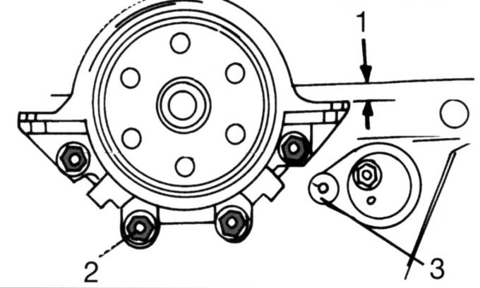
Pic. 88. Installation of the oil pump: 1 - normalized distance, 2 - screws
- Install the oil pump. Screw in the screws by hand and align the oil pump so that its housing is 0.3-0.8 mm below the surface of the cylinder block (pic. 88). The figure shows the engine produced before May 1998. Then measure in the manner shown in fig. 89. Insert the feeler gauge and finger-tighten the screws. They are tightened after the lower part of the crankcase is aligned.
Pic. 89. Measuring the distance between the pump and the cylinder block
- on the exhaust engine before May 1998, attach the oil pump. The following work must be performed within 20 minutes until the sealant dries. Lubricate the joints between the oil pump and cylinder block and the rear flange and cylinder block with sealant;
- Establish a new radial sealing ring in the case of the oil pump. The stuffing box is either driven in or a piece of pipe is used (which, according to the outer diameter, is mounted on a sealing ring) with a large washer and press the O-ring using a pulley screw into the housing until the outer surface is flush.
On engines manufactured since May 1998.
On these engines, align the bottom of the crankcase:
- lubricate the mating surfaces between the cylinder block and the oil pump (o-ring flange) sealant and install the crankcase with a new seal. Tighten the screws by hand;
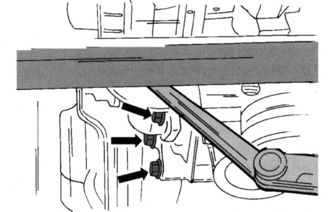
Pic. 90. Oil pump alignment on post-May 1998 engines
- install the steel ruler as shown in fig. 90 and align both parts of the cylinder block exactly flush. The displacement in the places shown by the arrows can be (with manual transmission installed) no more than 0.10 mm for the protrusion and up to a slot gap of 0.25 mm. If an automatic transmission is installed, the lower part must not protrude forward (completely flush) and the gap should not exceed 0.25 mm. Deviations in the gap are compensated by placing spacers, which are installed in the places shown in Fig. 91. In this case, if the gap is 0.26–0.50 mm, insert spacers with a thickness of 0.25 mm; if the gap is 0.51–0.75 mm, insert spacers 0.50 mm thick;
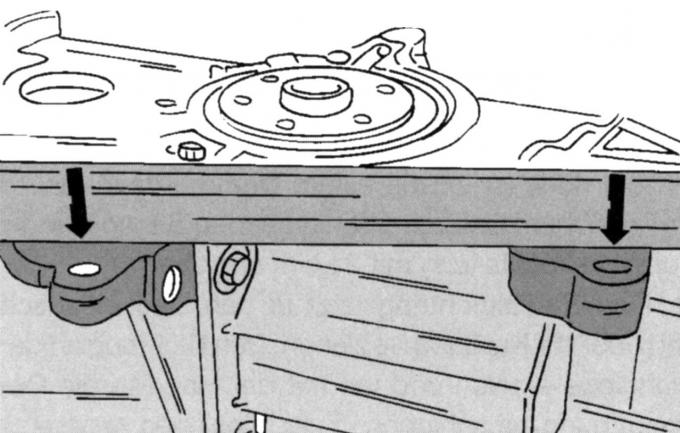
Pic. 91. Places for installing spacers
Note: From January 1999 only round spacers are used (top arrows).
- install the lower part of the crankcase with a new seal, check the alignment again as described and tighten the screws (four on one side and four on the other) torque 30 Nm.
On all engines
Install the oil suction tube with a new gasket. Tighten the suction pipe nuts to 10 Nm and the oil baffle nuts (until May 1998) torque 19 Nm;
- install the water pump with a new seal and tighten the four screws to 18 Nm;
Pic. 92. Installing the cover flange of the rear radial sealing ring of the crankshaft: 1 - size; 2 - screws; 3 - nut
- install the cover flange on the reverse side of the cylinder block without a radial sealing ring, so it must first be centered. Install the flange with a new gasket approximately in its seat and finger-tighten the screws. Move the flange so that the top edge is 0.3–0.8 mm below the surface of the cylinder head (pic. 92), and evenly around the circumference tighten the screws 2 to 16 Nm. Tighten nuts 3 of the crankshaft position sensor to 21 Nm;
- Establish a radial sealing ring in a flange of a cover and on a cranked shaft. Lubricate the working lip of the sealing ring with oil and insert the ring by hand into the hole in the cover. For refueling, a plate is used, which is fixed on the crankshaft flange with two screws. In the process of uniformly tightening the screws, the radial sealing ring is threaded until the plate touches the crankshaft;
- Install the oil pan as described in sec. «Engine lubrication system». Note the difference between pre and post May 1998 production engines;
- Install the flywheel in a well-cleaned crankshaft flange. Screws must always be replaced with new ones (covered with sealant). Markings must be visible on the flange of the crankshaft and flywheel;
- insert a screwdriver into the teeth of the ring gear to lock the crankshaft from turning. If the oil pan is mounted after installing the flywheel, a wooden block can also be inserted between the crankshaft and the crankcase to lock the shaft. Have an assistant support the engine and tighten the screws evenly around the circumference to 112 Nm (all engines). In the same way, the drive pulley of the automatic transmission is installed;
Note: If the old thread protector remains in the threaded holes, remove before installing the flywheel or drive pulley.
- install the clutch, as it is in the appropriate section. The screws are tightened with a torque of 30 Nm;
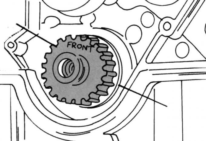
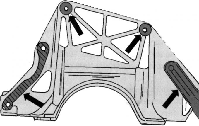
Pic. 93. Installing the crankshaft drive gear
- install the thrust washer on the front end of the crankshaft and put on the drive gear with the inscription «Front», pointing outward. After installation, the drive gear should be in the position shown in fig. 93. Turn the crankshaft so that the piston of the first cylinder is set approximately 20 mm below TDC;
- Install the cylinder head, camshafts and toothed drive belt, as described in subsection. 2.5;
- Establish covers of a gear driving belt. Tighten the bottom and middle cover screws to 7 Nm. Tighten both vertically inserted top cover screws to 4 Nm;
- screw the spark plugs;
- fix the water pump pulley (10 Nm), put on the crankshaft belt pulley and fix it with the screw (115 Nm). In this case, the crankshaft must be locked from turning;
- install a fan (10 Nm) and fix the ventilation wiring (23 Nm);
- install the thermostat housing with a new gasket and tighten the three screws to 21 Nm. Also fasten the ignition coil holder with the three screws to the same torque. Put the high voltage wires on the spark plugs in the correct sequence;
- Lubricate the rubber sealing ring of the oil filter with engine oil and screw the filter in until the sealing ring fits snugly. From this position, hand tighten another three quarters of a turn;
- screw in and tighten the drain plug with a new sealing ring;
- Install the exhaust manifold with a new gasket and evenly tighten the nine nuts in several steps to 16 Nm;
- Install the oil dipstick tube. Install the intake manifold. The air outlet hose can be directly connected to the collector pipe;
- Establish other details and knots removed from the engine, in an order, opposite to dismantling. Fill the engine with oil.
Axial clearance check (backlash) crankshaft
The axial clearance of the crankshaft must be checked before removing the shaft and during its assembly. The axial clearance of the shaft is determined on the bearing shell flanges of the middle bearing. If it exceeds the maximum allowable, replace the thrust half rings.
Check in the following order:
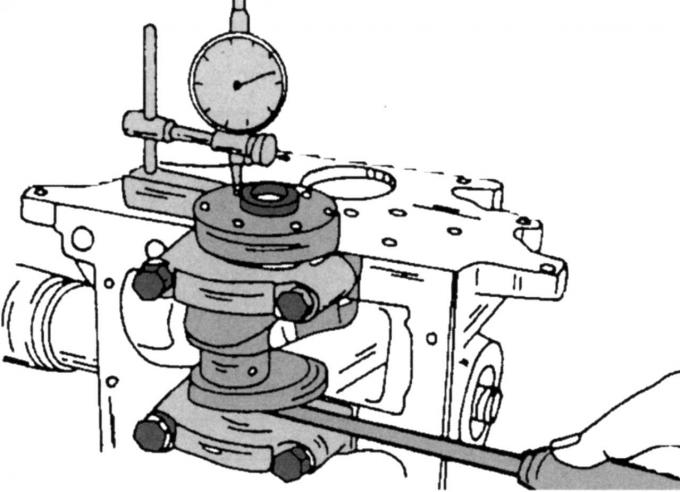
Pic. 94. Control of axial play of the crankshaft
- Install the engine as shown in fig. 94;
- Install a dial gauge on the flywheel side of the block. Install a measuring pin against the crankshaft flange or against the flywheel if fitted;
- Establish a screw-driver on the average bearing and wring out a cranked shaft in any direction;
- Set the dial indicator to zero and release the crankshaft. The value shown will be the end play. To replace the bearing shells, the crankshaft must be disassembled again.
Visitor comments