- Remove the storage battery;
- place the front of the car on supports and unscrew the protective shield (nine screws);
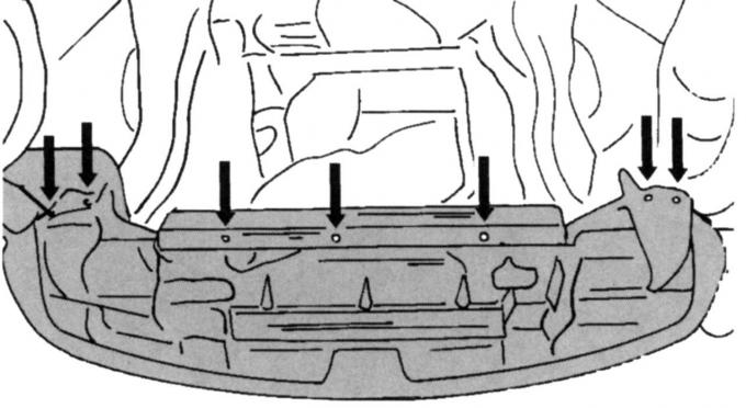
Pic. 52. Fixing the radiator lining
- Turn away facing in the bottom part of a radiator. It is fixed in the places shown in Fig. 52;
- remove the right forward wheel and facing of an internal part of a wheel niche (two screws);
- Remove poly V-belt;
Pic. 109. Left stop from turning (on vehicles with manual transmission): 1, 2 - screws
- on vehicles with a manual transmission, loosen the screws of the right anti-rotation stop by two turns. This is screw 1 (pic. 109) engine mounts and screws 2 subframes;
- on a car with an automatic transmission, loosen the middle screw of the right anti-rotation stop by two turns. Do the same on the vibration damper stop and stand;
- on all vehicles, disconnect the left stop from turning, but do not remove it;
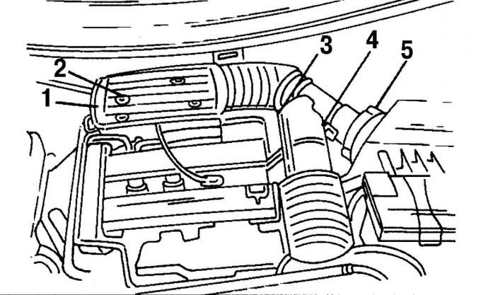
Pic. 22. Fixing the air intake pipes: 1 - mounting bolts, 2 - plug, 3 - plug, 4 - clamp, 5 - low pressure hose
- Remove an inlet branch pipe according to fig. 22. First remove the three fixing screws 1. Then remove the plug 3 from the sensor and on the same side remove the hose clamp 4. At the location indicated by number 2, remove the multi-pin plug from the intake air sensor. On the left side is a low pressure hose 5. Remove it;
- Remove the air filter. To do this, disconnect the ventilation hose between the filter and the cylinder head cover. Hang the rubber ring on the right, lift the air filter out of the mount and remove it;
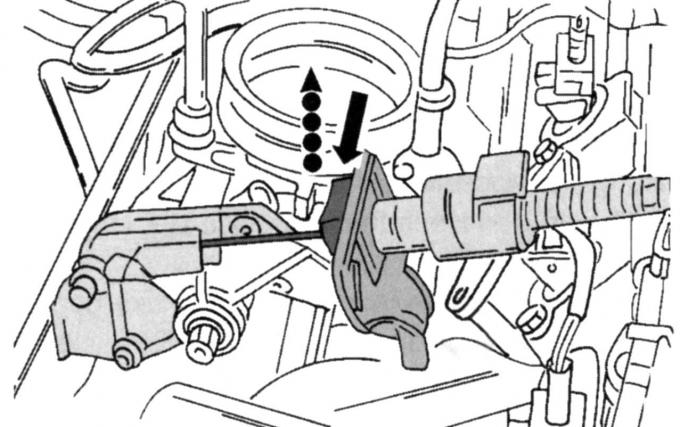
Pic. 54. Removing the throttle cable
- remove the throttle cable safety clip, disengage the cable from the lever and carefully lay the cable back (see fig. 54);
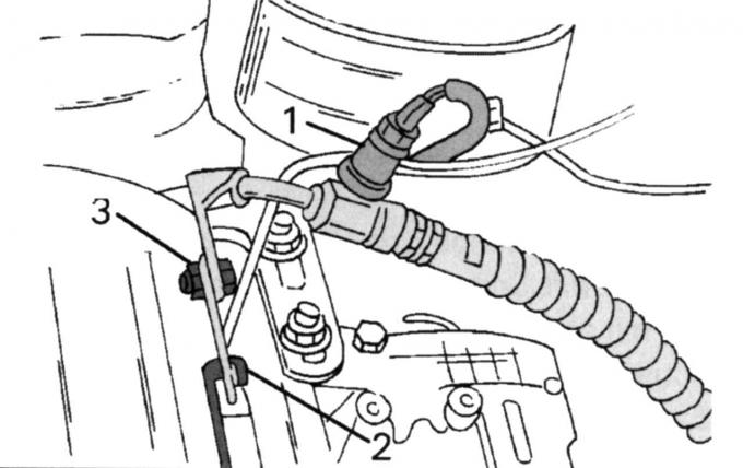
Pic. 110. An arrangement of some connections: 1 — the gauge switch of a steering with the amplifier; 2 - cable «masses» in the engine eye; 3 — the pipeline of a high pressure of a steering with the amplifier
- disconnect the following parts: plug 1 (pic. 110) steering gauge switch, cable «masses» 2 from the engine lug and high pressure hose 3 auxiliary steering pump;
- Disconnect the plug of the lambda probe from the engine mount;
- place a jack under the oil pan (with wooden spacer between car jack head and engine/drive) and raise the power unit until the engine mount is unloaded;
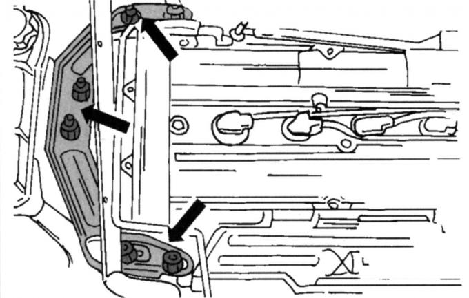
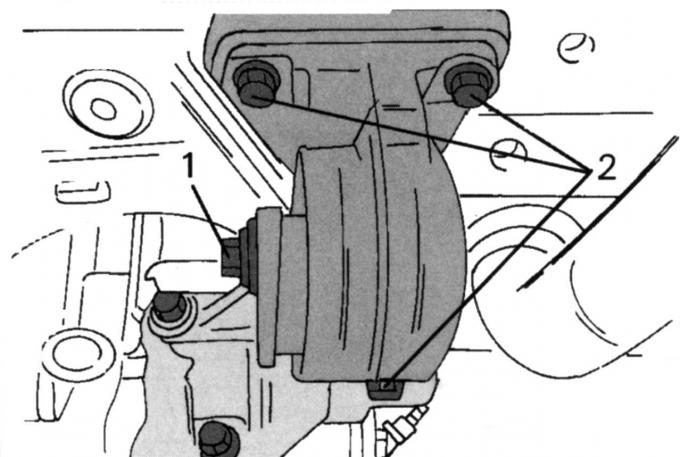
Pic. 32. Attachment points of the right engine mount
- Remove the right support of the engine. On fig. 32 shows how the support bracket is strengthened. Always replace self-locking nuts with new ones. After that, remove the bracket;
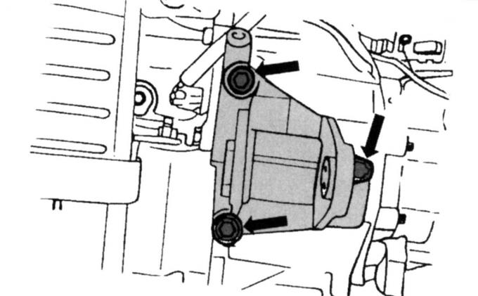
Pic. 111. Attachment points of the left stop
- with a manual gearbox installed, remove the anti-rotation support on the left side (pic. 111). To remove the stop, the power unit must be raised;
- Turn away screws of fastening of the console of the auxiliary pump of a steering and take out the console;
- Remove the generator suspension brackets;
- unscrew the middle and upper protective covers of the toothed drive belt after you have removed the drive belt tensioner;
- Remove the wire ends from the spark plugs. If you do not know the wires, mark the tips;
- unscrew the cylinder head cover (ten screws) and remove the gasket;
- Turn out spark plugs;
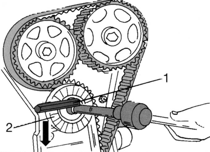
Pic. 59. The weakening of the tension of the toothed drive belt: 1 - nut; 2 - tension roller
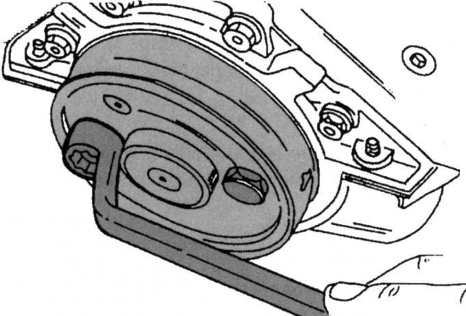
- Loosen the toothed drive belt. To do this, unscrew the nut 1 (see fig. 59) and install a suitable Allen key. Rotate the belt tensioner in the direction of the arrow and tighten the roller in the new position. Remove the toothed drive belt, do not oil it or break it if the belt is to be used again;
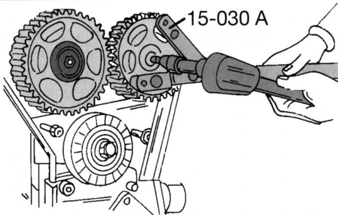
Pic. 45. Camshaft gear holding tool
- Loosen the fixing screws of both camshaft pulleys, keeping the shafts from turning. The clamp shown in fig. 45 is best suited for this purpose. Otherwise, insert a drift into one of the holes and carefully lock it against the cylinder head. Remove both pulleys, marking their place for subsequent installation;
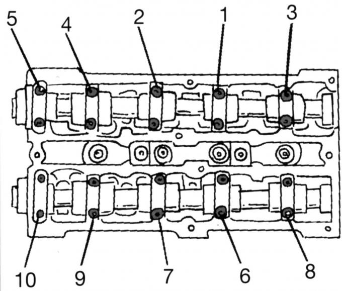
Pic. 46. The sequence of loosening the camshaft bearing caps
- Remove camshafts. To avoid deformation of the shafts, loosen the bearing caps in a certain sequence (see fig. 46). Accordingly, loosen the bearing cap nuts in the sequence shown by half a turn until they can be unscrewed by hand. Label the covers and remove them one by one. Carefully remove both camshafts and remove radial sealing rings;
- remove the poppet pushers one by one and lay them in the sequence required for installation, or mark them.
Reinstall the camshafts. The camshafts are marked. The intake valve shaft has an additional cam at the end for the camshaft position sensor. A small amount of sealant is required to seal the front camshaft bearing caps in connection with the cylinder head.
Installation of camshafts is carried out in the following order:
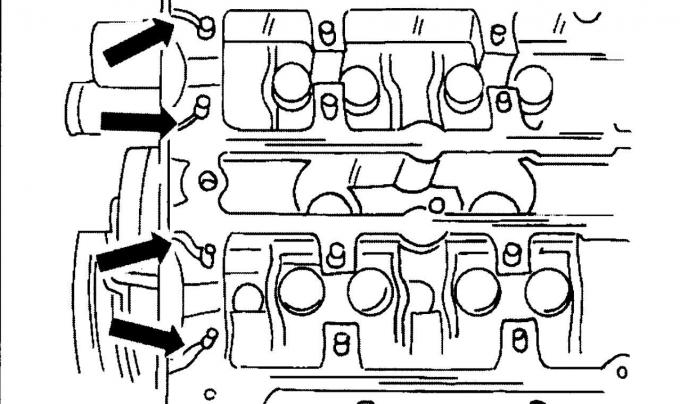
Pic. 61. Sealing points
- Grease with sealant the places on a head of the block of cylinders shown by arrows in fig. 61, for previous engines;
- Thoroughly lubricate the bearing necks of the camshafts with oil and insert the shafts into the corresponding stowage holes;
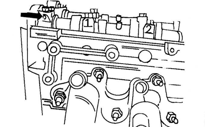
Pic. 62. Marking of camshaft covers
- Establish covers of bearings of camshafts in order of numbers. Marking is not quite usual, as the first cover is marked «0» and is on the output side. Subsequent numbering is carried out as shown in Fig. 62. All numbers must be visible from the outside;
- screw in all screws of covers and tighten by hand. Then tighten each respective pair of screws in the reverse order of that shown in fig. 46, half a turn. And again, in the same order, tighten the screws, pair by pair, with a torque of 10 Nm. Finally tighten all screws again in the same sequence with a torque of 19 Nm. Bearing caps must remain parallel to the surface of the cylinder head during tightening;
- Establish new epiploons of camshafts. Hammer the oil seal or use a piece of pipe with a diameter of the sealing ring. An M10 screw and a large washer are screwed onto the pipe to press the stuffing box onto the shaft. Lubricate the seal lips well;
- Fit the camshaft pulleys. The pulleys must rotate freely on the shafts;
Pic. 63. Caliber for adjusting the valve timing
- now you need a caliber to adjust the valve timing. Install this gauge as shown in fig. 63;
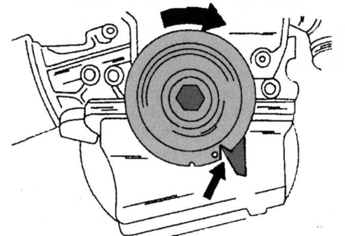
Pic. 64. Setting the crankshaft to top dead center (TDC)
- Turn the crankshaft so that the notch on the pulley is in the position shown in Fig. 64. This provision corresponds to TDC;
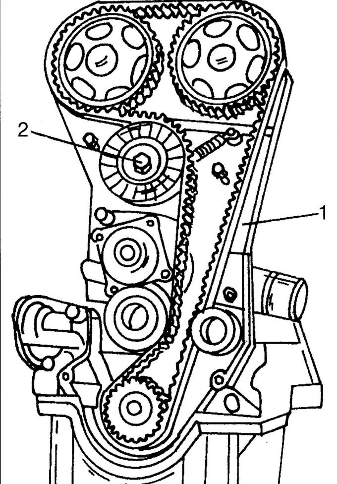
Pic. 66. Placement of the toothed drive belt: 1 - belt, 2 - screw
- Lay the toothed drive belt in a counterclockwise direction on the three pulleys and the belt tensioner. First lay the belt over the crankshaft pulley, keeping the teeth engaged, route the belt around the lower idler pulley and toothed drive belt tensioner on the left, and loop around the left camshaft pulley. Now, keeping the belt firmly in mesh with the teeth of the camshaft pulley, lay it on the right pulley and finally pass it around the inside of the right roller. Make sure that all teeth provide perfect meshing. Belt laying is shown in fig. 66. Now loosen nut 2, after which the belt tensioner will rush inward to provide the required tension;
- lock the camshaft pulleys from turning and tighten both screws to 68 Nm. In this case, the crankshaft must not rotate. After tightening the screws, turn the crankshaft two turns - the shaft will again be at TDC;
- tighten the belt tensioner screw to 38 Nm;
- check that the gauge is still aligned according to fig. 63 when the crankshaft is at TDC. Otherwise, loosen the corresponding camshaft pulley and move it slightly. Tighten the screw again to 68 Nm;
- Establish a cover of a head of the block of cylinders on a new sealing lining. Tighten the screws evenly around the circumference, first to 2 Nm and then to 7 Nm;
- screw in the spark plugs (15 Nm) and put high-voltage wires on candles in accordance with the order of operation of the cylinders;
- install protective shields. When doing this, pay attention to the fact that the middle cover is correctly located in the bottom cover;
- Install the drive belt pulley and tighten to 48 Nm;
- carry out all other works in the reverse order, taking into account the following tightening torques, Nm:
- middle stop screws
- from turning (Automatic transmission) 120
- right anti-rotation stop on the subframe (mechanical
- Transmission) 127
- right torque stop, middle screw (Manual Transmission) 48
- left anti-rotation stop (Automatic transmission) 48
- front suspension 83
- wheel screws 130
After installation, test drive the vehicle to reactivate the fuel injection/ignition control unit.
Note: If new camshafts were installed, the engine oil and oil filter must be changed.
Camshaft seals
Replace oil seals in the following order:
- provide access to the end of the camshaft with the drive gear so that you can unscrew the pulley of the corresponding shaft and remove it;
- unscrew the front cover of the bearing and remove the sealing ring;
- Apply sealant to the split surfaces of the front bearing cover and put the cover back on. Tighten the cover alternately from the right, then from the left with a torque of 10 Nm, and pull it out of this position again with a torque of 19 Nm;
- drive a new oil seal onto the camshaft or press it in with a piece of pipe with a diameter of the sealing ring. An M10 screw and a large washer are screwed onto the pipe to press the stuffing box onto the shaft. Lubricate the sealing lips well;
- Put the pulley on the camshaft. The pulley must rotate freely on the shaft;
- Install and tighten the toothed drive belt as described in the relevant subsection.
Rear crankshaft oil seal
To replace the oil seal, remove the gearbox, flywheel and clutch or drive pulley (automatic drive).
To pull out the oil seal, drill two small holes in the ring. Insert two self-tapping screws and carefully remove the ring (with a screwdriver and pliers).
Pic. 112. Installing the gland
Lubricate with oil a new O-ring along the sealing lip and the working surface of the crankshaft and press it into the crankcase. For pressing, a disk is used, which is reinforced with two screws on the crankshaft flange. By evenly tightening the screws, press in the radial sealing ring until the disc rests against the crankshaft flange (pic. 112).
After installing the stuffing box, install the flywheel and tighten the screws evenly around the circumference to 112 Nm. Install the clutch (see the relevant subsection) and reinstall the gearbox.
Visitor comments