Engines produced before May 1998.
Disconnect the battery;
- place the front of the car on supports;
- remove the mudguard under the car (nine screws);
- remove the right front wheel;
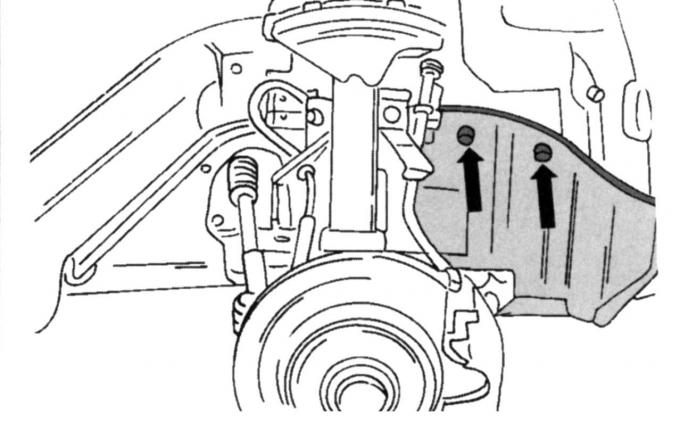
Fig. 96. Cover mounting locations on the inner side of the wheel arch
- on the inside of the wheel arch, unscrew the cover. It is secured in the places shown in Fig. 96;
- remove the poly V-belt as described in the relevant subsection;
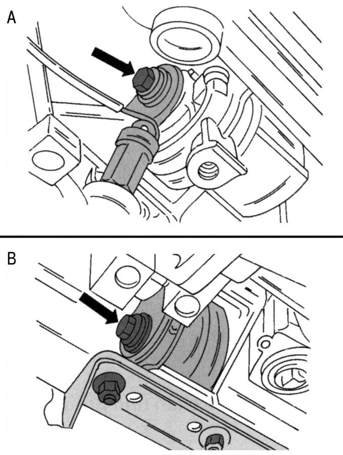
Fig. 97. Loosening the stop screws (on vehicles with automatic transmission): A - on the right side, B - on the left side
- on vehicles with a manual transmission, loosen the horizontally inserted screw of the right stop against rotation (similar to that shown in Fig. 97, B);
- on vehicles with an automatic transmission, loosen the screws (Fig. 97) of the left stop from turning;
- unscrew the screws of the liquid pump pulley and remove the pulley;
- lock the crankshaft from turning, unscrew the pulley screw and remove the pulley. If necessary, press with two levers to mount the tires;
- unscrew the lower protective cover of the toothed drive belt (three attachment points);
- lower the car onto its wheels;
- remove the air intake hose as described when removing the cylinder head;
- unscrew the expansion tank (two screws) and put it aside;
- place a jack under the oil pan (with a wooden spacer between the oil pan and the head of the car jack) and lift the power unit until the engine mount on the front side is unloaded;
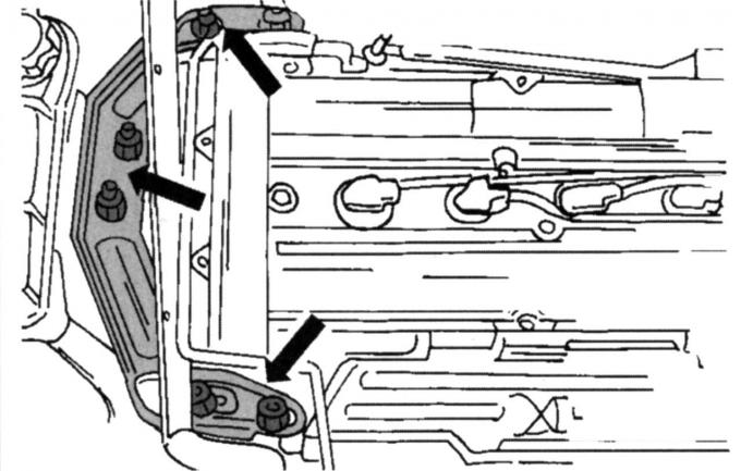
Fig. 32. Right engine mount mounting locations
- unscrew the engine suspension bracket shown in Fig. 32;
- release the lambda probe plug from the spring clip and remove it;
- unscrew the middle and upper protective covers of the toothed drive belt, removing the running roller of the poly V-belt;
- remove the spark plug caps and cylinder head cover (ten screws);
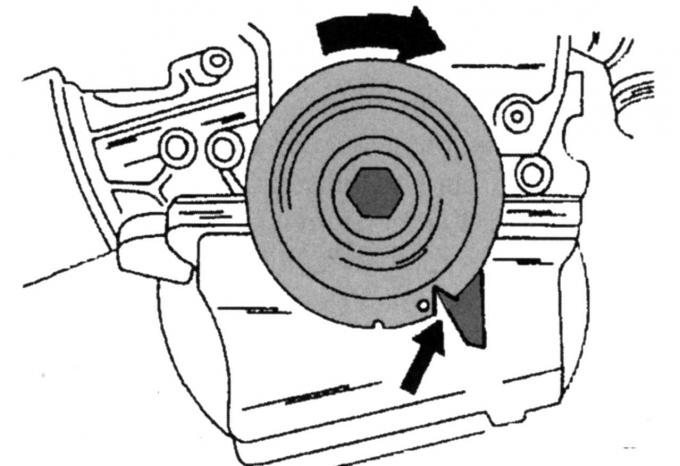
Fig. 64. Setting the crankshaft to top dead center (TDC)
- turn the crankshaft so that the cutout in the pulley is opposite the marking, as shown in Fig. 64;
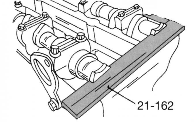
Fig. 63. Gauge for adjusting valve timing
- fix both camshafts in this position (see Fig. 63);
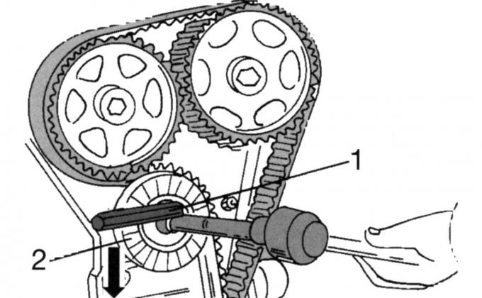
Fig. 98. Releasing the tension of the toothed drive belt: 1 — nut; 2 - roller
- loosen the toothed drive belt. To do this, loosen screw 1 (Fig. 98) and insert a suitable Allen key in the position shown in the figure. Turn the tension roller in the direction of the arrow and tighten the tension roller again in the new position. Remove the toothed drive belt;
Note: If you do not have a timing gauge, mark the pulleys and camshafts.
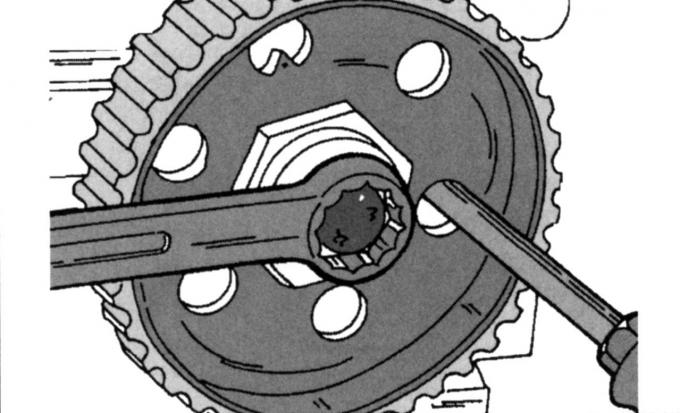
Fig. 99. Holding the camshaft drive gear from turning
- loosen the fastening screws of both camshaft pulleys, securing the shafts from turning. Insert a mandrel into one of the holes, as shown in Fig. 99, and carefully rest it against the cylinder head. The pulleys should turn freely on the shafts.
If you need to reinstall the same toothed drive belt, protect it from contamination with liquid or thick grease. Never clean the belt, you can wipe it with a dry cloth. After a very long run, check the camshaft pulleys for wear of the teeth. There should be no delamination on the belt.
When installing the toothed drive belt, proceed as follows:
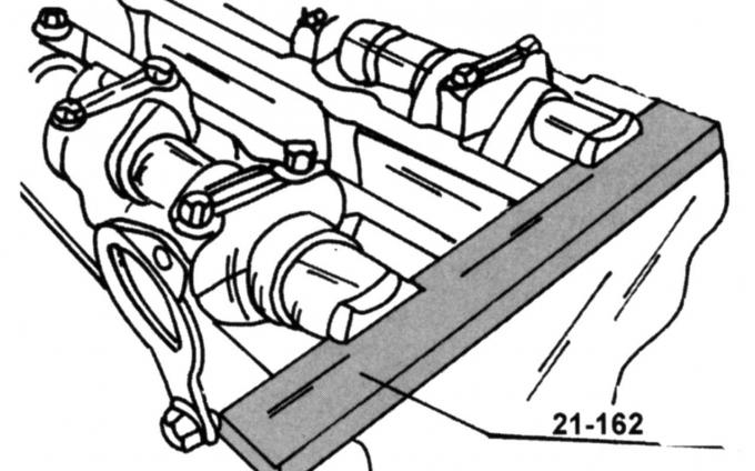
Fig. 100. Gauge (21-162) for adjusting the valve timing, installed on the camshafts
- insert the valve timing gauge as shown in Fig. 100;
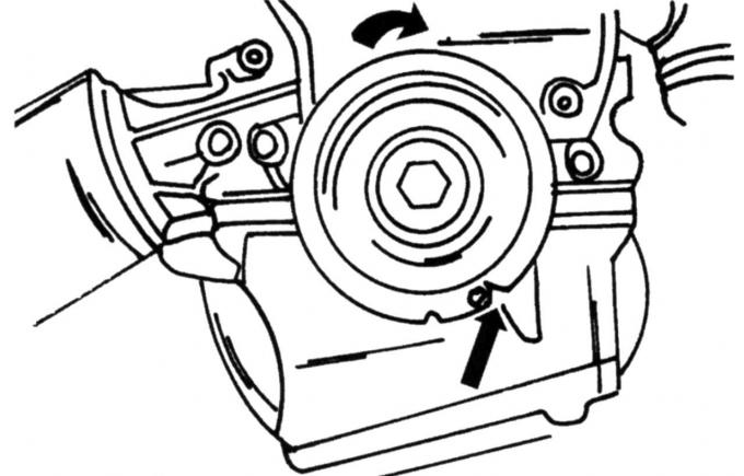
Fig. 101. Crankshaft in TDC position
- turn the crankshaft until the notch on the pulley is in the position shown in Fig. 101. It corresponds to TDC. With the toothed drive belt removed, turn the shaft very slowly so that the valves do not hit the pistons;
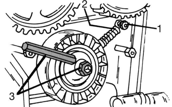
Fig. 102. Pre-tensioning of the belt tensioner: 1 — support bolt; 2 - tension spring; 3 - screw
- if the spring of the belt tensioner has been removed, it must be reattached. To do this, screw in the support bolt 1 (Fig. 102) and tighten it to a torque of 10 Nm, hang the spring 2 between the bolt and the belt tensioner. Insert the Allen key as shown in the figure and turn in the direction of the arrow. Then tighten the tension roller with screw 3 in the new position;
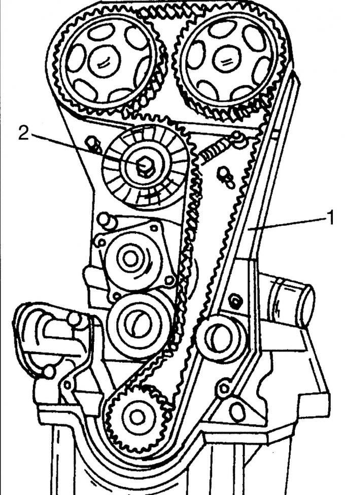
Fig. 66. Placement of the toothed drive belt: 1 - belt, 2 - screw
- Place the toothed drive belt on the three pulleys and the tensioner in a counterclockwise direction. First place the belt on the crankshaft timing gear. Keeping the teeth engaged, place the belt on the left around the lower guide roller and the tension roller and loop it around the left camshaft pulley. Keeping the belt firmly engaged with the teeth of the camshaft pulley, place the belt over the right pulley and finally around the inside of the right running roller. Make sure that all the teeth are engaged. Loosen nut 2 (see Fig. 66), after which the device will provide the required belt tension. Tighten the nut to a torque of 38 N·m;
- lock the camshaft pulleys from turning and tighten both screws to a torque of 68 Nm. The crankshaft should not turn. After tightening the screws, turn the crankshaft two turns until the piston is again at TDC;
- check that the gauge is still aligned according to Fig. 63 when the crankshaft is set to TDC. If not, loosen the corresponding camshaft pulley and move it slightly. Retighten the screw to 68 Nm;
- install the cylinder head cover with a new sealing gasket. Tighten the screws evenly around the circumference, first to 2 Nm, then to 7 Nm;
- screw in the spark plugs (15 Nm) and put the high-tension wires on the spark plugs in accordance with the firing order of the cylinders;
- Install the middle protective cover of the toothed drive belt and then the upper cover. The middle cover must be freely hooked onto the lower cover. Screw on the left side of the poly V-belt roller (48 Nm);
- Secure the engine mount with new self-locking nuts. The center punch mark must be aligned with the mark on the suspension bracket. Tighten the four nuts on the engine and one nut on the engine mount to 83 N·m;
- lower the car onto its wheels;
- install the expansion tank of the cooling system and the intake pipe. After that, put the car back on the supports;
- on vehicles with an automatic transmission, tighten the middle screw of the right stop to a torque of 120 N·m (see Fig. 97, A), on vehicles with a manual transmission, tighten the screws of the left and right stop to the same torque;
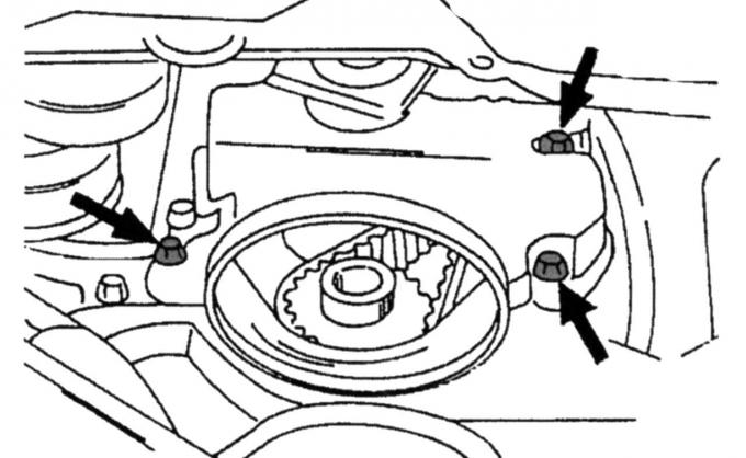
Fig. 103. Fastening points of the lower cover of the toothed drive belt (on engines produced since May 1998, one screw is used on the left and one on the right, respectively)
- screw on the lower protective cover of the toothed drive belt (Fig. 103);
- screw on the fluid pump belt pulley;
- fit the crankshaft belt pulley (vibration damper) and lock the crankshaft from turning (engage the gear). Tighten the screw to a torque of 115 N·m;
- install the poly V-belt and tension it as described in the relevant subsection;
- perform all other work in the reverse order of removal. Make sure that the removed plugs, high-voltage wire tips to the spark plugs, hoses, etc. are reconnected in their original places. Do not forget that the coolant is drained;
- tighten the wheel nuts (130 Nm) if the front wheel has come loose;
Engines produced since May 1998.
- disconnect the battery;
- place the front of the car on supports;
- unscrew the mudguard under the car (nine screws);
- remove the right front wheel;
- on the inside of the wheel arch, unscrew the cover. It is secured in the places shown in Fig. 96;
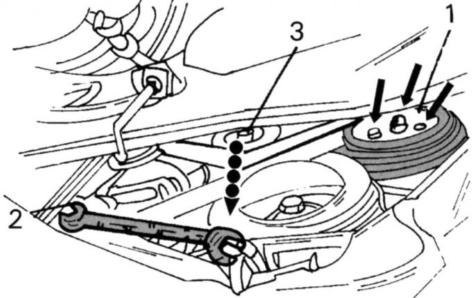
Fig. 104. Removing the poly V-belt on engines produced since May 1998: 1 — screws; 2 - key; 3 - tension roller
- remove the poly V-belt (Fig. 104);
- lock the crankshaft from turning, unscrew the pulley screw and remove the pulley. If necessary, press with two levers to mount the tires;
- unscrew the lower protective cover of the toothed drive belt (two attachment points - left and right);
- remove the expansion tank;
- place a jack under the oil pan (with a wooden spacer between the oil pan and the head of the car jack) and lift the power unit until the engine mount on the front side is unloaded;
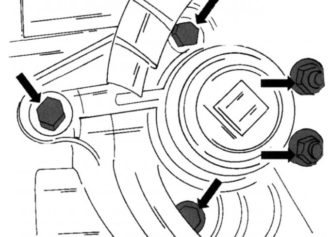
Fig. 70. Front engine mount mounting locations
- unscrew the engine mount shown in Fig. 70. Pre-mark the exact position for installing the mount;
- unscrew the upper protective cover of the toothed drive belt (two screws on the left and right), but do not remove it;
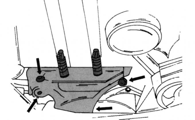
Fig. 105. Attachment points of the middle toothed belt cover
- remove the middle toothed belt cover together with the engine mount bracket (Fig. 105). Now you can remove the top cover;
- remove the high-voltage wires from the spark plugs one by one (pull the tips straight and upward). Unscrew the cylinder head cover (ten screws) and remove the sealing gasket;
- remove the spark plugs;
- check that the piston is set to TDC (see Fig. 64);
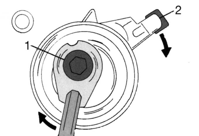
Fig. 71. Loosening the toothed drive belt: 1, 2 — screws
- loosen the toothed drive belt (see Fig. 71). To do this, unscrew nut 1 and insert a suitable Allen key in the position shown in the figure. Turn the belt tensioner in the direction of the arrow. Loosen screw 2 by four turns and disengage the belt tension roller. Remove the toothed drive belt, do not stain it with oil or break it if you are going to use it again;
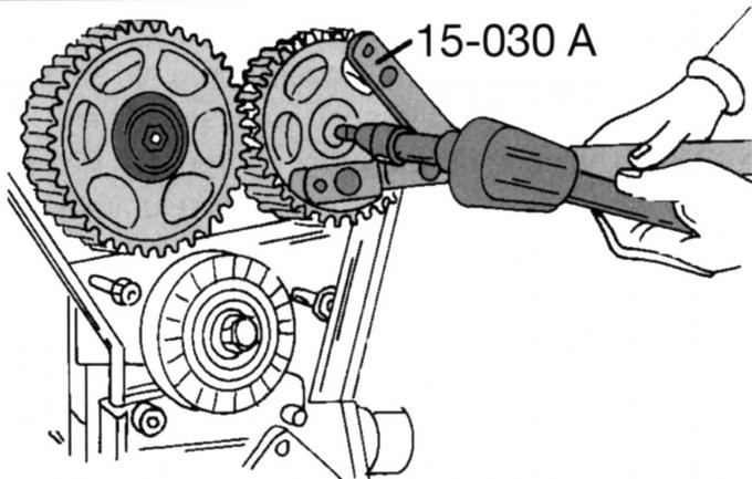
Fig. 45. Tool for holding camshaft gears
- Loosen the mounting screws of both camshaft pulleys, holding the shafts from turning. The clamp shown in Fig. 45 is best suited for this purpose. Otherwise, insert a drift into one of the holes and carefully lock it against the cylinder head. Remove both pulleys, marking their location for subsequent installation.
Note: If you do not have a timing gauge, mark the pulleys and camshafts.
If you need to reinstall the same toothed drive belt, try not to contaminate it with liquid or thick grease. Never clean the belt, you can wipe it with a dry cloth. After a very long run, check the camshaft gears for wear of the teeth. There should be no material peeling off the belt.
When installing the toothed drive belt, proceed as follows:
- to fix the crankshaft at the service station, a special gauge is used, which is screwed into the cylinder block; you will need the valve timing gauge already mentioned on engines produced before May 1998. Insert this gauge as shown in Fig. 100;
- turn the crankshaft until the notch on the pulley is set to the TDC position shown in Fig. 101. With the toothed drive belt removed, turn the shaft very slowly so that the valves do not hit the pistons;
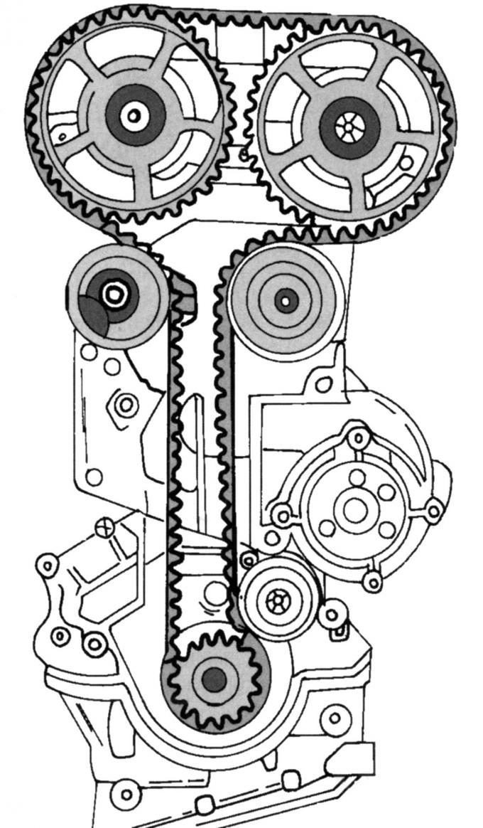
Fig. 106. Location of the toothed drive belt on engines produced before January 1999.
- up to January 1999, the toothed drive belt was routed as shown in Fig. 106, with an additional tension roller at the bottom. Route the toothed drive belt in a counterclockwise direction over the three pulleys and the belt tensioner. First route the belt over the crankshaft pulley, keeping the teeth engaged, pass the belt from the top left around the tension roller and both camshaft pulleys, and then route the belt as shown around the inside of the right and bottom rollers. Make sure all the teeth are engaged;
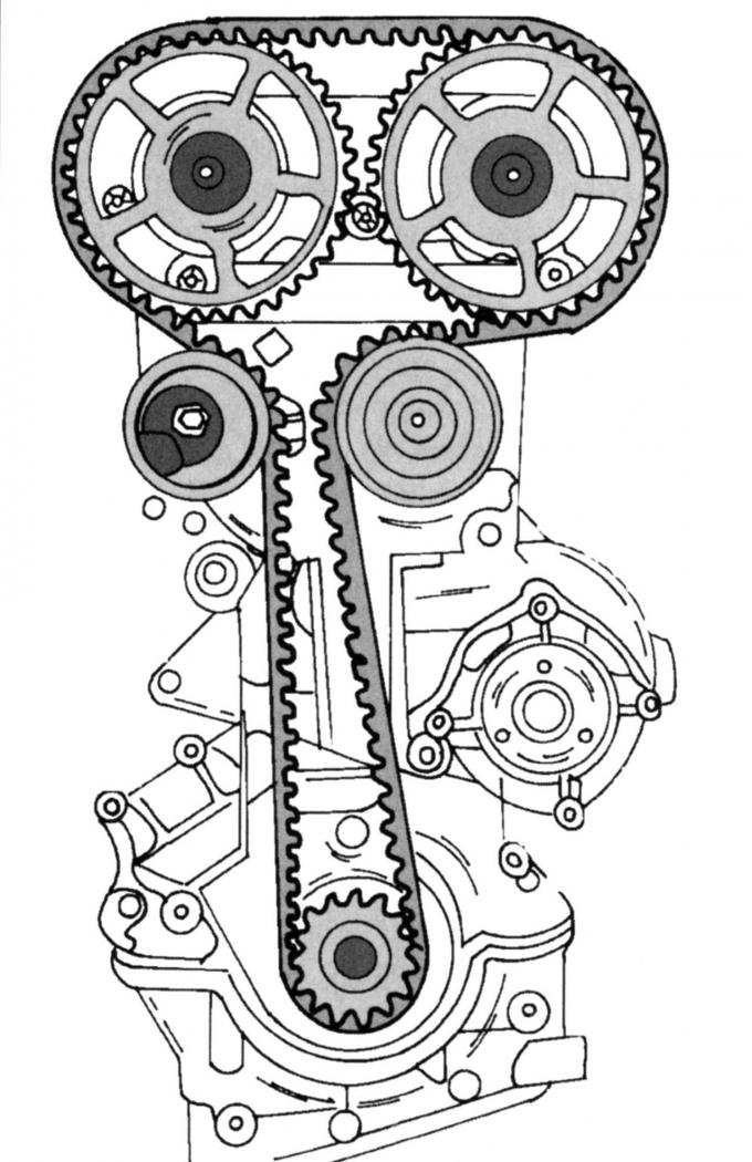
Fig. 107. Location of the toothed drive belt on engines produced since January 1999.
- starting from January 1999, the lower roller was no longer used, the belt was laid as shown in Fig. 107. The toothed drive belt is laid in the manner described above;
Note: The timing belt tensioner has a tongue. When routing the belt, do not hook it onto the metal cover.
- in accordance with Fig. 71, hook the belt tensioner onto the metal cover and tighten the screw by hand;
- tension the toothed drive belt by turning the tension roller to the left (in the direction of the arrow) until the marked arrow and the line coincide. In this position, tighten the screw in the middle of the belt tensioner to a torque of 25 Nm;
- lock the camshaft pulleys from turning and tighten both screws to a torque of 68 Nm. The crankshaft should not turn. After tightening the screws, turn the crankshaft two turns until it is again at TDC;
- check that the gauge is still aligned according to Fig. 63 when the crankshaft is set to TDC. If not, loosen the corresponding camshaft pulley and move it slightly. Retighten the screw(s) to 68 N·m;
- install the cylinder head cover with a new sealing gasket. Tighten the screws evenly around the circumference, first to 2 Nm, then to 7 Nm;
- screw in the spark plugs (15 Nm) and put the high-tension wires on the spark plugs in accordance with the firing order of the cylinders;
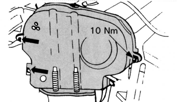
Fig. 108. Fastening locations of the upper protective cover of the toothed drive belt on engines produced since May 1998.
- install the upper toothed belt cover together with the middle cover. Tighten the middle cover to the engine mount support bracket to a torque of 50 Nm. Check that the upper cover seal is tight and that the screws (Fig. 108) are tightened to a torque of 10 Nm;
- install the front engine mount. Tighten the screws and nuts to 83 Nm. After this, you can remove the jack;
- install the expansion tank;
- install the lower timing belt cover and tighten both screws to 7 Nm;
- fit the crankshaft belt pulley (vibration damper) and lock the crankshaft from turning; engage the gear. Tighten the screw to a torque of 115 N·m;
- install the poly V-belt and tension it as described in the relevant subsection;
- perform all other work in the reverse order of removal. Make sure that the removed plugs, high-voltage wire tips to the spark plugs, hoses, etc. are reconnected in the same places;
- tighten the wheel mounting nuts (130 Nm) if the front wheel was removed.
Checking the technical condition of camshafts
If scratches or cracks are found, replace the camshaft(s) or cylinder heads.
To check the diameter and out-of-roundness, measure the camshaft bearing journals with a micrometer. Compare the values found with the internal diameters of the bearing holes in the cylinder head and with the technical data (see appendix) to determine the condition of the parts.
The camshaft bearing play can be measured in the same way as the crankshaft main bearing play, using a plastic rod called "Plastigage". Screw on the bearing caps to flatten the rod and then unscrew them again. Measure the width of the flattened rod and compare with the required value, which is 0.020–0.070 mm.
If the clearance is too large, replace the camshaft and/or cylinder head.