Contents: Radial clearance ↳ Axial clearance ↳
Radial clearance
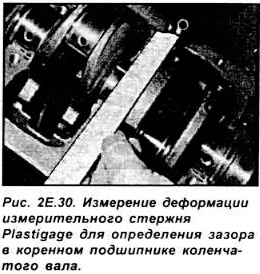
The radial clearance in the main and connecting rod bearings of the crankshaft is measured using special Plastigage measuring rods made of artificial material. The measuring rod, laid along the journal (main or connecting rod) and clamped in the bearing, is subjected to flattening. The radial clearance in the bearing can be determined (based on the appropriate scale, on the packaging of the measuring rods) depending on the width of the deformed rod (see Fig. 2E.30).
Measuring conditions with Plastigage measuring rods:
- the necks and liners must be dry and thoroughly degreased;
- the crankshaft must not change its position during the installation and removal of measuring rods;
- the measuring rod should be placed in half of the bearing shell, at a greater distance from the oil hole in the bearing shell or shaft journal;
- bearing caps must be installed by hand and their bolts must be tightened to the appropriate torque: do not strike the caps;
- only the bearing cap in which the radial clearance is measured should be tightened; it is not possible to measure clearances in all main bearings at the same time.
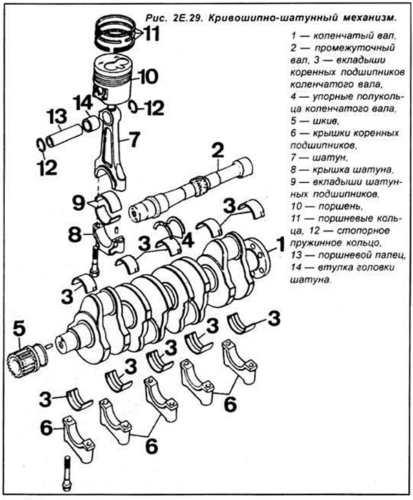
Install the liners on the main bearings in the engine cylinder block and install the crankshaft into them.
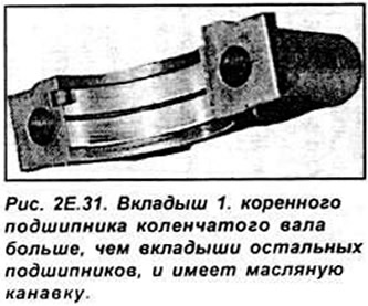
Note. The shells of the first main bearing (on the timing drive side) are larger than the shells of the other bearings and both have an oil groove (see Fig. 2E.31). In the other bearings, the shells on the cylinder block side have an oil groove, and on the cover side have a smooth surface.
Place a Plastigage measuring rod on the first main journal.
Install the main bearing cap together with the liner and tighten the mounting bolts to the specified torque.
Carefully remove the bearing cap and measure the width of the deformed measuring rod using the scale supplied with the measuring rods and determine the radial clearance in the bearing based on the table or graph.
Compare the measured value with the required clearance value. If the measured clearance exceeds the permissible value, repair liners should be used.
Measure the clearance in the remaining main and connecting rod bearings in a similar manner.
Axial clearance
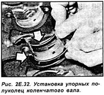
After installing the crankshaft in the cylinder block, install the crankshaft thrust half rings (the oil grooves should be directed outward from the main bearing - Fig. 2E.32). bearing caps and tighten them to the appropriate torque.
Place the dial indicator tip on the end of the crankshaft and measure its axial clearance (see Fig. 2E.33).
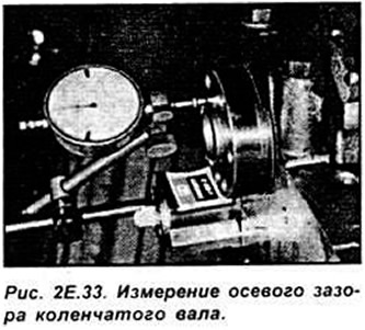
Compare the measured values with the required values. If the gap exceeds the permissible value, then repair thrust half rings of correspondingly greater thickness should be used.
(The text is available on the specified website info portal: FordBook)