Withdrawal
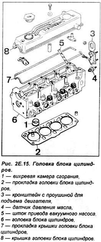
Disconnect the ground wire from the battery. Drain the coolant from the cooling system.
Disconnect the air supply line to the turbocharger, the crankcase ventilation flex pipe from the cylinder head cover, and the air supply line between the air filter and the radiator shroud (the pipeline is put on the fitting).
Disconnect from a head of the block of cylinders all elastic pipelines of system of cooling. Disconnect the brake booster vacuum line and oil return line from the vacuum pump. Disconnect the electrical wires from the glow plugs, oil pressure sensor, coolant temperature sensor, and radiator fan thermal switch. Disconnect the fuel return lines from the injectors. Disconnect the injection lines from the fuel pump and injectors. Disconnect the vacuum line from the fuel pump. Disconnect the thermostat cover from the cylinder head. Disconnect the fuel lines from the pump and fuel filter. Disconnect the vacuum line from the intake manifold. Disconnect the oil lines from the turbocharger and oil pump. Disconnect the turbocharger from the exhaust manifold. Disconnect the bracket supporting the front exhaust pipe from the transaxle cross member.
Disconnect the oil return line from the turbocharger and engine block. Remove the coolant pump and alternator V-belts.
Unscrew the mounting bolt on the left side of the lower casing of the gas distribution drive.
Unscrew the bolt securing the upper casing of the timing system drive on the right side so that it can be removed. Remove the three spring hooks of the upper casing of the timing system drive. remove the mounting bolts and lower the casing down Remove from the cylinder block, at the height of the crankshaft pulley, the plug of the control hole of the mandrel for installing the crankshaft. Rotate the crankshaft. so that the notch of the fuel pump pulley is in position "12 hours" (see fig. 2E.11).
Install a mandrel in the cylinder block to set the crankshaft to the TDC position of the piston of 1 cylinder (see fig. 2E.13).
Rotate the crankshaft counterclockwise until it stops against the mandrel. Remove the timing belt tensioner pulley. and then the timing belt.
Remove passive pulley (increasing angle of engagement of the toothed belt) and the rear cover of the gas distribution system drive. Unscrew nozzles Remove a cover of a head of the block of cylinders.
Remove the ten cylinder head bolts in reverse order to tightening them (see fig. 2E.26). Remove the cylinder head.
Disassembly
Remove the intake and exhaust manifolds. Unscrew from the cylinder head two brackets with holes for lifting the engine and the oil pressure sensor.
Remove the vacuum pump by unscrewing in series (and at the same angle) two mounting bolts.
Remove the bearing caps No. 2 and 4 of the camshaft. Unscrew the nuts of the remaining camshaft bearing caps by 1/4 turn.
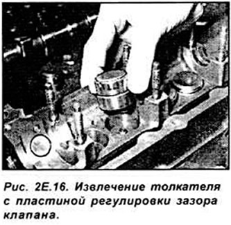
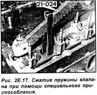
Remove the camshaft bearing caps together with the top bearings, seals and remove the camshaft. Remove the pushrods together with the valve clearance adjusting plates and position them so that they can be installed in the same sockets in the cylinder head in which they were previously installed during assembly. Remove the vacuum pump drive pusher. With the aid of a device (21.024) compress the individual valve springs and remove the crackers. Remove the tool and remove the upper spring retainers, springs and valves.
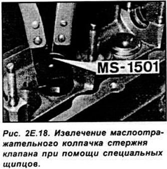
With special forceps (MS-1501) Remove the valve stem seals from the valve stems.
Examination
After disassembling the cylinder head, thoroughly wash all parts, check their technical condition and evaluate their suitability for further work. All gaskets should be replaced and the valves should be lapped.
Assembly
Lubricate the valve stems with engine oil and insert them into the guides. Wrap the ends of the valve stems with adhesive tape so that they do not damage the working edges of the caps and, using tool 21.007, install the caps on the valve stems. Install the valve springs, upper plates and, using tool 21.024, compress the springs and insert the cotters.
Lubricate the vacuum pump drive rod with engine oil and insert it into the hole in the cylinder head. Lubricate the tappets with oil and install them, together with the valve clearance adjusting plates, into the sockets in the cylinder head in which they were previously installed. Insert the lower camshaft bearing shells into the sockets in the cylinder head and lubricate them with engine oil. Install the camshaft on the bushings, the eccentric on the end of the shaft must point upwards.
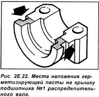
Install the upper bearing shells in the camshaft bearing caps and lubricate them with oil. Place washers under the cylinder head so that the valves can move in the guides. Apply sealing paste SPM-4G911 ZF/G to the sealing surface of bearing No. 1 of the camshaft (from the drive side of the gas distribution system).
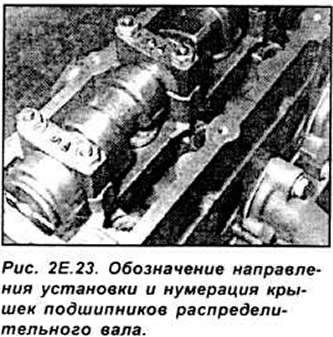
Install the camshaft bearing caps No. 1, 3 and 5. Designations on them (arrows) should be directed forward (towards the drive of the gas distribution system). Tighten the camshaft bearing cap nuts by hand.
Tighten the camshaft bearing cap nuts #3, then #1, then #2 with a 180°wrench.
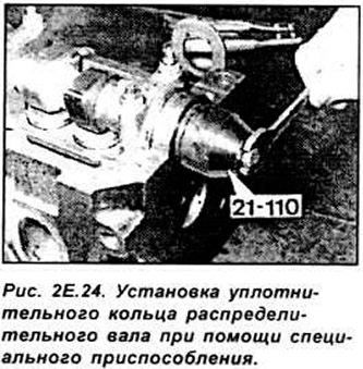
Repeat the last operation until then. until the covers are exactly in place. Install bearing caps #2 and 4 with plastic hammer blows. Tighten the bolts of all camshaft bearing caps to the correct torque. Lubricate the camshaft O-ring with engine oil and install it using tool 21110.
Install the vacuum pump with the O-ring and tighten its mounting bolts consistently and evenly to the correct torque.
Screw two brackets with holes for engine lifting to the cylinder head and screw in the oil pressure sensor.
Screw the exhaust and intake manifolds to the cylinder head, together with new gaskets, and tighten the bolts and nuts of their fastening to the appropriate torque.
Installing the cylinder head and adjusting the gas distribution system
Attention. The contact surfaces of the cylinder block gasket and the head must be smooth, clean and without scratches or damage.
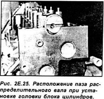
Check the condition of the bottom surface of the cylinder head, this surface is not repairable (not regrindable). Before installing the head, make sure that the groove at the end of the camshaft eccentric is horizontal (parallel to the bottom plane of the cylinder head), and the larger part of the eccentric is directed upwards (see fig. 2E.25).
Measure the protrusion of the pistons above the top plane of the cylinder block.
Depending on the protrusion of the pistons, select the appropriate thickness of the head gasket. Install the head gasket on the cylinder block as follows. to the side with the inscription "TOR" was on top Install the head on the cylinder block.
Insert the mounting bolts into the corresponding holes in the cylinder head.
Attention. When installing the cylinder head, use new mounting bolts.
Tighten the cylinder head bolts to the correct torque in the correct sequence (see fig. 2E.26).
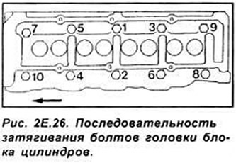
Attention. Since March 1992, 1.8 dm3 engines use a different type of cylinder head bolts. which have an M12 thread and Torx T70 heads. These bolts must be tightened in the same sequence. as the old type bolts (see fig. 2E.26) the following points:
- 1 stage: 10 Nm
- Stage 2: 100 Nm
- Step 3: unscrew the bolt "1" 180°
- Step 4: Tighten the bolt "1" torque 70 Nm
- Step 5: Tighten the bolt "1" additionally by 120°
- Step 6: Tighten as described above (steps 3-5) the rest of the bolts. following the correct tightening sequence
Screw the glow plugs into the cylinder head, tighten them to the correct torque, and connect their electrical wires.
Screw the injectors into the cylinder head together with new thermal insulation washers, with the convex side towards the head.
Establish a back right casing of a drive of system gas distribution with a tensioner roller. Install the rear left cowl with the middle pulley. Check if the rubber ring of the flexible pipe is in its place on the casing.
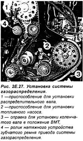
Install the camshaft pulley and insert the tool (1. fig. 2E.27).
Check if the crankshaft of the engine touches the mandrel at TDC position of the piston of 1 cylinder. Install a new timing belt. Tension the timing belt as follows. Loosen the bolt securing the pulley to the camshaft, then unscrew the idler pulley bolt half a turn. The tensioner roller under the influence of the spring will move to the toothed belt of the timing system drive. and then tighten all the above bolts. Remove all installation tools.
Turn the crankshaft two full turns in the direction of its working rotation and set it in position. in which the notch of the fuel pump pulley is in position "12 hours" (see fig. 2E.11).
Rotate the crankshaft in the opposite direction and install the cutout of the fuel pump pulley in position "11 o'clock" (see fig. 2E.11).
Screw the mandrel into the control hole of the cylinder block to set the piston of 1 cylinder to TDC and carefully rotate the engine crankshaft (in the direction of its working rotation) up to the stop in the mounting mandrel.
Insert the camshaft pulley setting tool into the hole provided for it (see fig. 2E.27).
Unscrew the bolts securing the middle pulley and tensioner roller by one turn; then push the length of toothed belt on the opposite side of the tensioner pulley in its direction and release the belt.
Tighten all mounting bolts.
Remove all installation tools. then screw the plug into the control hole of the adjusting mandrel in the engine block. Establish a casing of a drive of system gas distribution. Install and tension the alternator drive V-belt. Install the water pump drive V-belt. Connect the oil return line from the turbocharger to the engine block.
Screw on the front exhaust pipe.
Screw the exhaust pipe bracket to the transaxle cross member Install new gaskets and connect the oil supply lines to the pump and turbocharger. Connect the vacuum pipe screwed to the fuel pump to the intake manifold. Check and, if necessary, adjust the valve clearance.
Install the cylinder head cover with gasket. Then follow the rest of the steps in reverse order to the process of removing the cylinder head, paying attention to:
- compliance with the appropriate tightening torques for bolts and nuts;
- installing a new thermostat cover gasket.
- removal of air from the fuel system.
- filling the cooling system and removing air from it.
- checking the tightness of all connections.
Visitor comments