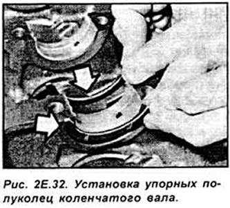
Insert the main bearing shells. Lubricate the main and connecting rod journals of the shaft and the main bearing shells with oil.
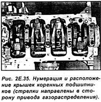
Install the crankshaft on the main bearing shells in the engine block. Install the main bearing caps (with the arrows on the caps pointing toward the timing drive) together with the shells. Lubricate the threads of the new main bearing cap bolts with oil. Tighten the main bearing cap bolts to the specified torque.
If piston rings were removed, install them on the pistons with the "TOP" inscription facing the piston bottom. Position the ring locks at an angle of 120°.
Lubricate the smooth surface of the cylinders, the side surface of the pistons and the piston rings with oil. Install the half-liners in the connecting rod bases.
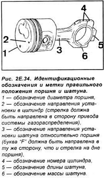
Install the piston-connecting rod assemblies in the cylinders, paying attention to the installation marks (see Fig. 2E.34):
- the connecting rod and cover are marked with the number of the cylinder in which they are installed (cylinder No.1 on the timing drive side).
- the arrow on the bottom of the piston and the letter "F" on the side surface of the connecting rod journal must be directed towards the valve timing drive.
- the connecting rods are divided into four selection groups differing in the distance between the axes of the head and base holes, which allows to limit to a minimum the difference in the piston protrusion above the upper plane of the cylinder block (and thus the difference in the compression ratio in individual cylinders), the selection group of the distance between the connecting rod axes is designated by the letters "A", "B", "C" and "O" stamped on the connecting rod caps (the letter "A" refers to the shortest connecting rods).
- connecting rods are divided into two selection groups depending on their weight: "light" and "heavy", all connecting rods in the engine must belong to the same weight group.
Insert the half bearing shells into the connecting rod caps.
Lubricate the connecting rod bearings and shaft journals with oil. Install the connecting rod caps, paying attention to their designation (see Fig. 2E.34).
Insert new connecting rod cap bolts and lubricate their threads with oil.
Tighten the connecting rod cap bolts to the specified torque. Lubricate the O-ring gasket of the oil supply pipe to the oil pump with oil. Install the oil supply pipe and check that the gasket is in the correct place. Install the crankshaft rear cover with a new gasket reaching the bottom plane of the engine cylinder block. Tighten the rear cover bolts.
Using tool 21.148 and the mounting bolt, install the crankshaft pulley, the front plate of the cylinder block together with a new gasket.
Lubricate the front crankshaft journal and the pulley O-ring with oil.
Install the pulley onto the crankshaft, making sure that the keyway with the key in the journal is exactly opposite the keyway in the pulley.
Lubricate the intermediate shaft and bearing bushings in the cylinder block, as well as the front support plate, with oil.
Install the intermediate shaft together with the support plate into the cylinder block.
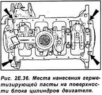
Apply a thin layer of sealing paste to the indicated areas (see Fig. 2E.36) and install the oil pan with a new gasket. First insert the four oil pan corner mounting bolts and tighten them by hand, then insert and tighten the remaining oil pan mounting bolts by hand. Tighten the bolts — except for the corner bolts — to the specified torque. Tighten the corner bolts of the oil pan to the specified torque. Install the coolant pump with a new gasket. Fill the oil pump with about 10 cm³ of oil. Install the oil pump. Screw on the oil filter. Install the engine cylinder head.
Install the generator. Install the fuel pump. Install the pulley onto the crankshaft. Install the flywheel onto the crankshaft.
Install the clutch onto the flywheel. Install the starter. Install the exhaust manifold.