Special tool
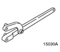 | Universal wrench for holding flanges 205-072 (15030A) |
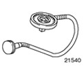 | Goniometer 303-174 (21540) |
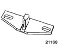 | Flywheel locking tool 303-204 (21168) |
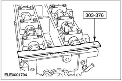
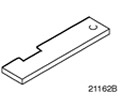 | Camshaft Alignment Tool 303-376 (21-162V) |
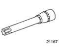 | Socket wrench for cylinder head bolts 303-392 (21167) |
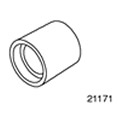 | Crankshaft oil seal installation tool 303-395 (21171) |
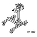 | Assembly stands 303-435 (21187) |
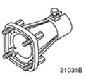 | Support bracket for 303-435 303-435-06 (21031B) |
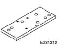 | Base plate for 303-435-06 303-435-14 (21212) |
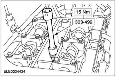
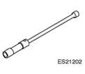 | Spark Plug Wrench 303-499 (21202) |
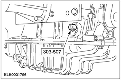
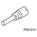 | Pin for setting the top dead center of the crankshaft 303-507 (21210) |
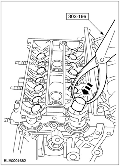
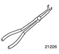 | Pliers for spark plug connectors 303-622 (21226) |
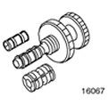 | Clutch disc alignment tool 308-204 (16067) |
General equipment:
- Studs, M8x20
- steel ruler
- Repair shop crane
| Name | Specification |
| Engine oil | WSS-M2C912-A1 |
| Sealant for camshaft bearing caps | WSK-M2G348-A2 |
| Sealant for joints of the sealing surfaces of the cylinder block, crankshaft rear oil seal, oil sump | WSE-M4G323-A4 |
| Oil Pressure Switch Thread Sealant | WDK-M2G349-A7 |
| Lubricant (spark plug thread - Never Seeze) | ESE-M1244-A |
| Silicone Grease | ESE-M1C171-AA |
Assembly
All cars
1.
CAUTION: Crank mechanism components, pistons and cylinder liners must not be replaced individually. For more information, please refer to the chapter Description and function available in this section.
Preparatory operations:
- Coat the threads and contact surfaces of all bolts and washers with engine oil prior to installation.
- All mating surfaces and reusable components should be thoroughly cleaned and inspected for damage.
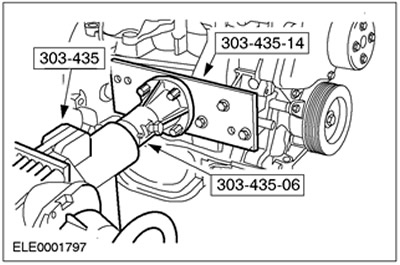
2. Fix the cylinder block with the crank mechanism (short block) at the assembly stand. Use special tools 303-435-14 and 303-435-06.
3.
NOTE: Correct the fit of the oil seal housing.
Connect the new rear oil seal housing with seal and install the crankshaft position sensor support (TFR).
4. Install the CKP sensor.
Vehicles with manual transmission.
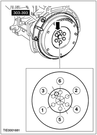
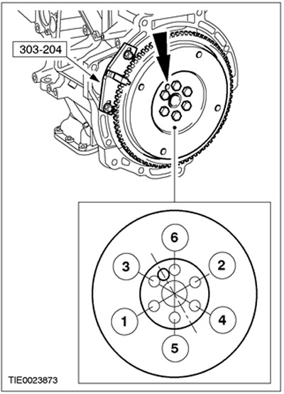
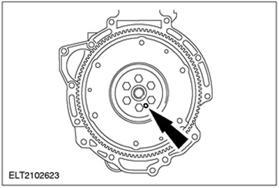
5.
NOTE: Observe tightening sequence and position of flywheel locating pin.
Install the flywheel.
- Connect the flywheel, block it from turning with the special tool and tighten the nuts, working in two stages in accordance with the prescribed tightening sequence.
- Stage 1: 30 Nm
- Stage 2 using special tool 303-174: 80 degrees
Remove the engine rotation limiter center bolt (right front axle).
6.
NOTE: Observe the tightening sequence and position of the drive plate locating pin.
Install the drive disk.
- Install the drive plate, lock with the special tool and tighten in two steps in the tightening sequence shown.
- Stage 1: 30 Nm
- Stage 2 using special tool 303-174: 80 degrees
All cars
7.
NOTE: Align oil pump drive shaft with crankshaft.
Connect the oil pump and oil inlet line with a new gasket.
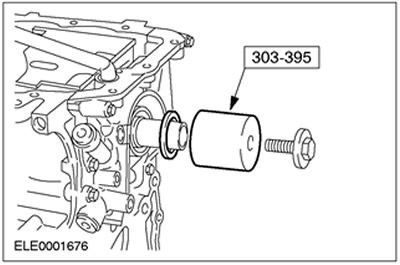
8.
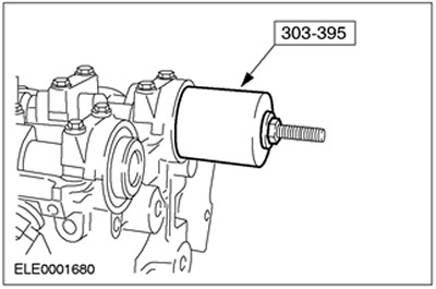
NOTE: Lubricate the oil seal lip and crankshaft journal with engine oil.
Install the crankshaft front oil seal. Use a special tool.
Vehicles manufactured up to 11.1999
9.
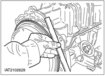
NOTE: Apply sealant 10mm behind the mating surface joints.
Apply sealant to the mating surface of the cylinder block and mating surface of the crankshaft rear oil seal housing.
10. Check the position of the oil sump.
- Install the oil pan with a new gasket and hand tighten the bolts.
- Using a steel straightedge, align the oil sump so that the cylinder block is flush with the oil sump on the flywheel side.
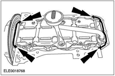
Vehicles manufactured since 12.1999
11.
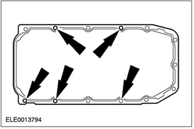
CAUTION: Use hairpins. If the sealant gets into the blind holes, the engine crankcase may be damaged.
Install five studs (M8x20) into the specified blind holes.
12.
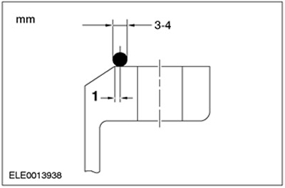
NOTE: Connect the oil sump within ten minutes of applying the sealant.
Apply a 3mm bead of sealant to the oil pan flange.
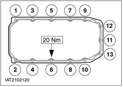
13.
NOTE: Tightening sequence.
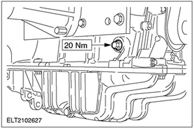
Tighten the oil pan bolts in two steps.
- Stage 1: 10 Nm
- Stage 2: 20 Nm
- Unscrew the pins.
Vehicles manufactured up to 11.1999
14.
NOTE: Tightening sequence.
Tighten the oil pan bolts.
Vehicles with manual transmission
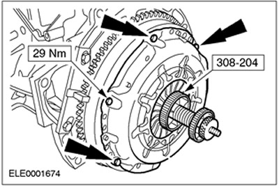
15. Install the clutch.
- Center the clutch pressure plate on the driven plate. Use a special tool.
- Evenly, working in a crisscross fashion, tighten the six bolts.
- Remove the special tool.
All cars
16.
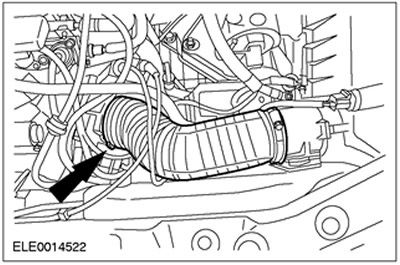
CAUTION: Knock Sensor Wire (KS) must not touch the cylinder head and crankcase ventilation hose (approximately position "10/11 hours").
Connect the crankcase ventilation hose and knock sensor.
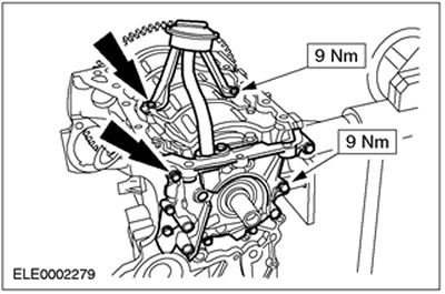
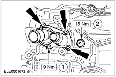
17.
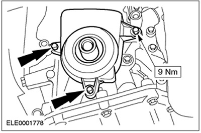
CAUTION: Check thermostat and replace if necessary. See Section 303-03 for more information.
NOTE: The thermostat oil seal should only be replaced if necessary.
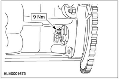
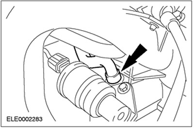
NOTE: Apply sealant to the threads of the oil pressure switch.
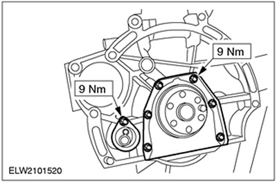
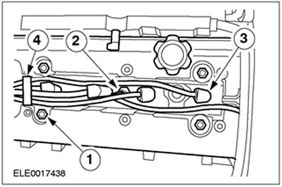
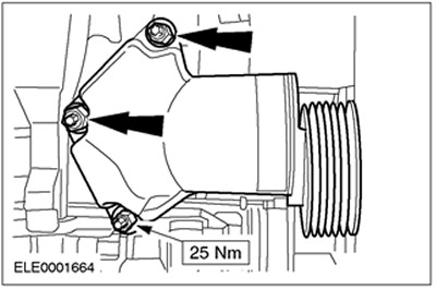
Connect the thermostat housing along with a new gasket and oil pressure switch.
- 1. Thermostat housing with new gasket
- 2. Oil pressure switch
18.
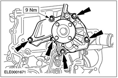
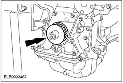
CAUTION: Be careful not to damage the coolant pump impeller.
Install the coolant pump. Use a new gasket.
19.
NOTE: Tightening sequence.
NOTE: The cylinder head is mounted on two guide bushings.
NOTE: Removed cylinder head bolts can be reused.
Install the cylinder head.
- Make sure all mating surfaces are clean.
- Install a new cylinder head gasket.
- Align the cylinder head and tighten the bolts, working in three stages in the sequence shown.
- Stage 1: 15 Nm
- Stage 2: 30 Nm
- Stage 3 using special tool 303-174: 90 degrees
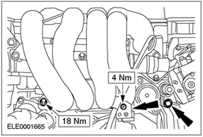
20. Install the three lower intake manifold bolts and connect the oil dipstick tube. Lock the knock sensor connector (KS) on the oil dipstick tube.
21. Connect the PCV hose.
22.
NOTE: Install the valve lifters and shims in the correct sequence.
Install the valve lifters. If necessary, use suitable shims to adjust the valves.
23. Bring the piston of cylinder No. 1 to a position approximately 25 mm before top dead center. The flywheel must be in the position shown.
24.
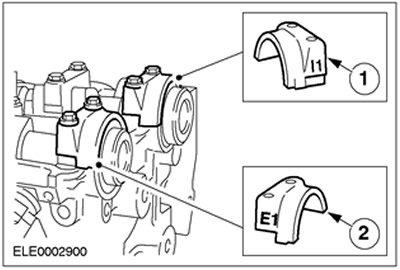
NOTE: Identification numbers are located on the outer surface of the camshaft bearing caps.
Apply sealant to the indicated locations on the #1 camshaft bearing cap and cylinder head mating surface.
25.
CAUTION: Reinstall the camshafts so that none of the cams is in the full lift position.
NOTE: The exhaust camshaft has an additional cam for the camshaft position sensor (SMR).
Install the camshafts. Coat the camshafts and camshaft bearings with engine oil before installing.
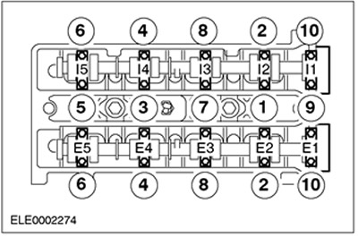
26.
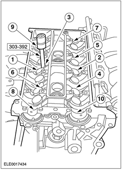
NOTE: Identification of the camshaft bearing caps starts next to the timing belt with E1 on the exhaust side and I1 on the intake side.
NOTE: Tightening sequence.
Install the camshaft bearing caps and tighten the bolts, working in three stages.
- Step 1: Half a turn on each bolt until the camshaft bearing cap is in contact with the cylinder head.
- Stage 2: 7 Nm
- Stage 3: 45 degrees
27. Install a new camshaft oil seal. Lubricate the camshaft journals and oil seal lip with engine oil.
28. Install the timing belt inner cover.
29. Install the camshaft pulleys so that they can turn.
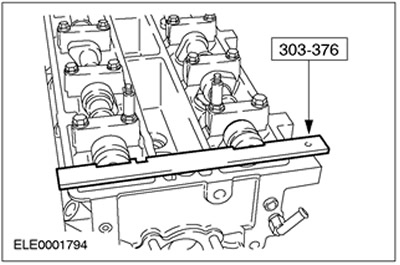
30. Rotate the camshafts to top dead center for cylinder #1. Turn the camshafts with a 21 mm open-end wrench until the special tool can be inserted.
31.
NOTE: If the special tool cannot be inserted, rotate the crankshaft back approximately 20 degrees counterclockwise.
Rotate the crankshaft to top dead center for cylinder #1.
- Remove the plug from the alignment pin hole and screw in the special tool.
- Carefully turn the crankshaft in a clockwise direction until it rests against the special tool.
32. Install the pulley on the crankshaft.
33. Put on the timing belt. Slide the timing belt back into place, starting at the crankshaft pulley and working counterclockwise.
34. Connect the lower timing belt cover.
35.
NOTE: For more information, please refer to the chapter Description and operation available in this section.
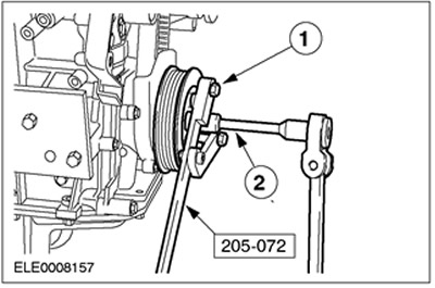
Install the crankshaft pulley/damper. Use a new bolt.
- 1.Connect the special tool with two bolts (M10x40 and M10x45) and corresponding nuts.
- 2. Tighten the bolt, working in two stages.
- Stage 1: 40 Nm
- Stage 2 using special tool 303-174: 90 degrees
Timing belt tensioner with eccentric
36. Install the timing belt tensioner.
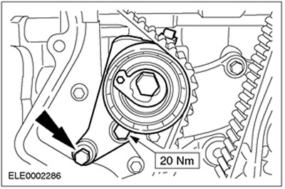
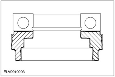
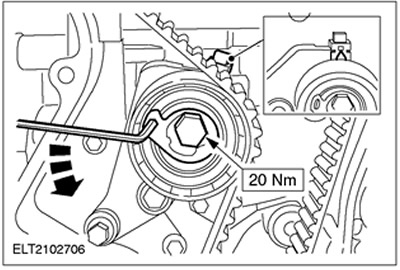
37.
NOTE: Do not rotate the eccentric when tightening. Hold using a socket wrench.
Tension the timing belt.
- With socket wrench (for internal hexagon) 6 mm turn the eccentric in a counterclockwise direction until the arrow is exactly aligned with the middle of the square cutout.
- Tighten the bolt.
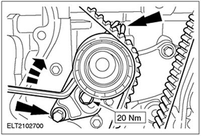
Groove Timing Belt Tensioner
38. Install the timing belt and tighten it.
- Screw in the bolts and tighten them by hand.
- Using a socket wrench, turn the tensioner so that the arrow aligns exactly with the center of the rectangular hole.
- Tighten the bolts.
All cars
39.
CAUTION: Do not tighten the camshaft pulley while holding the camshaft from turning with special tool 303-376.
NOTE: Do not rotate the crankshaft and camshafts.
Tighten the bolts on the camshaft pulleys.
40. Unscrew special tool and remove special tool 303-376.

41.
NOTE: If special tool 303-507 cannot be installed, rotate the crankshaft approximately 20 degrees counterclockwise.
Check valve timing.
- Rotate the crankshaft two turns clockwise and bring it to top dead center.
- Screw in special tool 303-507.
- Carefully turn the crankshaft in a clockwise direction until it rests on the special tool.
- Use special tool 303-376 to check the top dead center position.
- Remove special tools 303-376 and 303-507.
42.
NOTE: Only if special tool 303-376 cannot be inserted.
Adjust the valve timing.
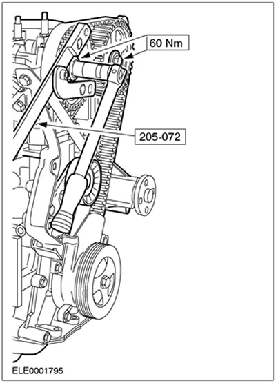
- Loosen the pulley on the problem camshaft using special tool 205-072 to prevent rotation.
- Turn the camshaft by the hex key using a 21mm open-end wrench until the special tool 303-507 can be inserted.
- Tighten the pulley on the camshaft; the crankshaft must remain at top dead center.
- Remove special tool 303-376 and unscrew special tool 303-507.
- Check the valve timing again as previously described.

43. Screw the plug into the alignment pin hole.
44. Adjust valve clearances. For more information, refer to the Valve Clearances chapter in this section.
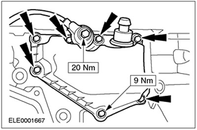
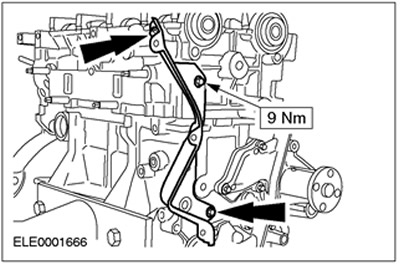
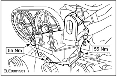
45. Connect the engine support bracket.
46. Apply grease to the threads of the spark plugs and install them using the special tool.
47.
CAUTION: When installing a new cylinder head, check the cylinder head cover for damage and install a new cover if necessary.
CAUTION: To avoid damage to the spark plug connector seal, use a blunt object to apply silicone grease (e.g. plastic clamp).
CAUTION: Attach the spark plug connector using a straight line force.
NOTE: Coat the inside of the spark plug connector with silicone grease to a depth of (5-10) mm.
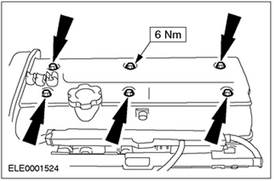
Install the cylinder head cover.
- 1. Tighten the cylinder head cover bolts, working in two stages. Stage 1: 3 Nm. Stage 2: 10 Nm.
- 2.Connect the cylinder head temperature sensor connector (SNT).
- 3. Connect the spark plug connector.
- 4.Install the high voltage wire clamp.
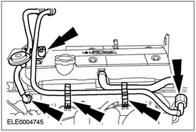
48. Install the upper cylinder head cover plate (if it was taken).
49. Install fuel lines. Install the hose holder.
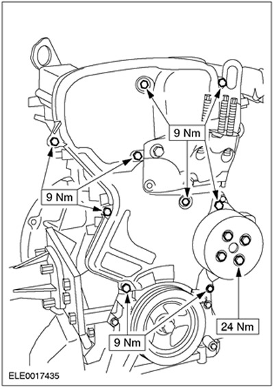
50. Install the timing belt top cover.
- Timing belt cover
- intermediate pulley
- Coolant pump pulley
Vehicles without air conditioning
51. Install the drive belt tensioner.
All cars
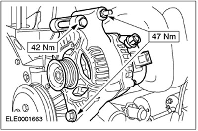
52. Install the generator.
53. Bring the crane and, using a special tool, hook the engine to it.
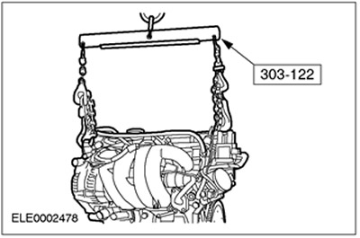
54. Remove the engine from the assembly stand. Disconnect special tools.
Visitor comments