Contents: Removal ↳ Installation ↳
Special tool
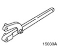 | Universal Flange Holding Wrench 205-072 (15030A) |
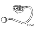 | Protractor 303-174 (21540) |
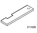 | Camshaft Alignment Tool 303-376 (21162B) |
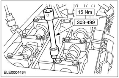
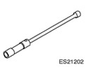 | Spark Plug Wrench 303-499 (21202) |
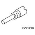 | Crankshaft Top Dead Center Pin 303-507 (21210) |
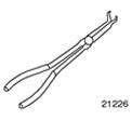 | Spark Plug Pliers 303-622 (21226) |
General equipment: Rolling jack.
| Name | Specification |
| Clamps | |
| Lubricant (for spark plug threads - Never Seeze) | ESE-M1244-A |
| Silicone grease | ESE-M1C171-AA |
Removal
All cars
1. Disconnect the ground cable from the battery. For additional information, refer to Section 414-01.
2. Loosen the bolts on the coolant pump pulley.
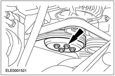
3. Raise the vehicle. Refer to Section 100-02 for additional information.
4. Remove the drive belt cover.
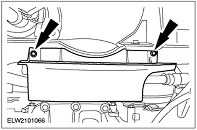
5. Loosen the drive belt tension and remove it.
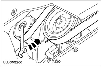
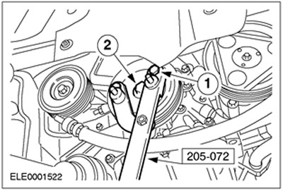
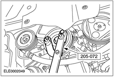
6. Remove the pulley/damper from the crankshaft.
- 1. Install the special tool using two bolts: M10x40 and M10x45 - and nuts.
- 2. Unscrew the bolt.
- Lock against rotation using a special tool.
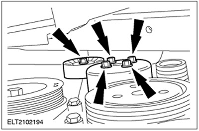
7. Remove the coolant pump pulley and the drive belt idler pulley.
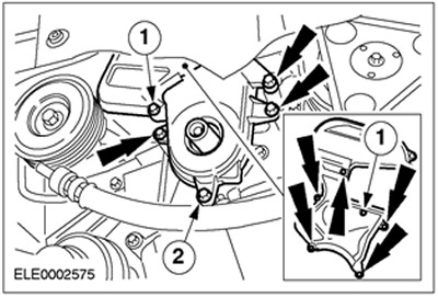
8. Remove the bolts from the timing belt cover.
- 1.Timing belt upper cover
- 2. Lower timing belt cover
- Remove the bottom cover.
9. Lower the vehicle.
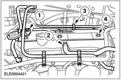
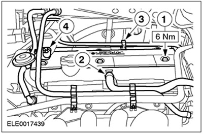
10. Remove the cylinder head cover plate (if equipped).
- 1. Release the fuel lines.
- 2. Disconnect the crankcase ventilation hose.
- 3. Release the carbon filter vacuum line bracket.
- 4. Unscrew the bolts (six bolts).
11.
CAUTION: When disconnecting the spark plug connector, do not pull on the wire. If necessary, remove the ignition coil to avoid bending the wire. Before removing, slightly rotate the spark plug connector to release the gasket.
CAUTION: Disconnect the spark plug connector using straight-line force only.
CAUTION: Do not damage the cylinder head cover gasket, as it cannot be replaced separately.
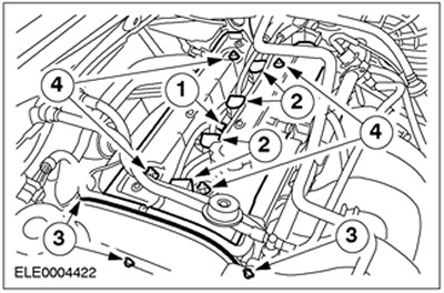
Remove the cylinder head cover by moving it straight up.
- 1. Disconnect the plug connector of the cylinder head temperature sensor (CHT).
- Release the CHT sensor plug connector clamp.
- 2. Disconnect the high tension wires from the spark plugs.
- For angled spark plug connectors, use special tool 303-622.
- 3. Remove the three bolts from the upper timing belt cover.
- 4. Unscrew and remove the nuts.
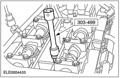
12. Remove the spark plugs. Use a special tool for removal.
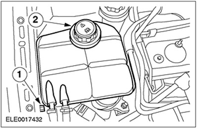
13. Disconnect the expansion tank of the cooling system.
- 1. Unscrew the bolt.
- 2. Release the expansion tank of the cooling system and place it aside.
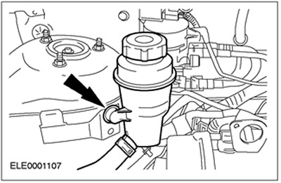
14. Release the power steering fluid reservoir and set it aside.
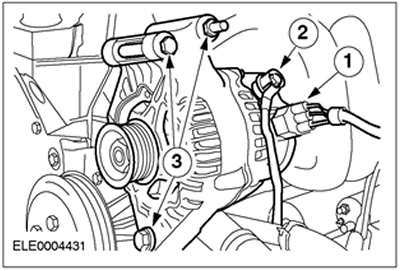
15. Remove the generator and place it aside.
- 1. Disconnect the plug connector.
- 2. Disconnect the positive cable.
- 3. Disconnect the generator.
- Disconnect the studs.
16. Place a trolley jack with wooden blocks under the oil pan and lift it slightly to relieve the load on the front engine mount.
17. Remove the engine mount.
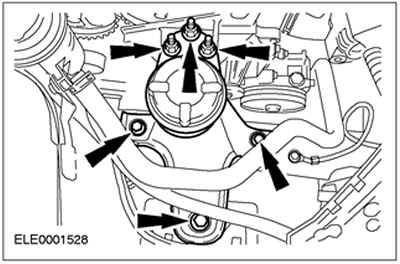
18. Remove the upper timing belt cover.
19. Remove the front engine mount bracket (shown with the engine removed).
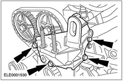
Timing Belt Tensioner with Eccentric
20.
NOTE: If the timing belt is to be reused, mark the direction of its movement.
Loosen and remove the timing belt (shown with the engine removed). Remove the bolt.
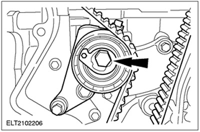
Timing Belt Tensioner with Groove
21.
NOTE: When reusing the timing belt, mark the direction of its movement.
Loosen and remove the timing belt (shown with the engine removed). Remove the bolts.

Installation
All cars
1. Set the crankshaft to 20 degrees before top dead center.
2.
CAUTION: Use a special tool to prevent them from turning.
Loosen the bolts enough to allow the camshaft pulleys to rotate on the shafts.
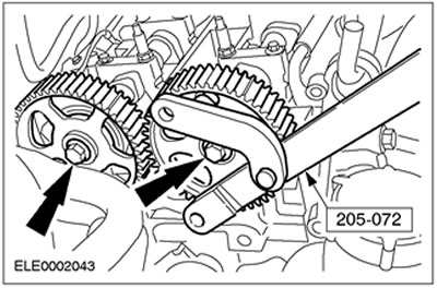
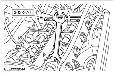
3. Turn the camshafts to the top position for cylinder No.1 and insert the special tool. Turn the camshafts by the hexagonal drive using a 21 mm open-end wrench until the special tool can be inserted.
4.
NOTE: Mark the direction of movement.
Install the timing belt. Starting at the crankshaft pulley and working counterclockwise, slide the timing belt into place.
5. Connect the lower timing belt cover (shown from below).
6.
NOTE: Use a new bolt.
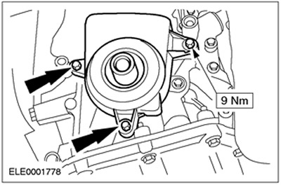
Install the pulley/damper onto the crankshaft.
- Tighten the bolt, working in two stages.
- Stage 1: 40 Nm
- Stage 2 (using special tool 303-174): 90 degrees
7.
NOTE: If the special tool cannot be inserted, turn the crankshaft back counterclockwise approximately 20 degrees.
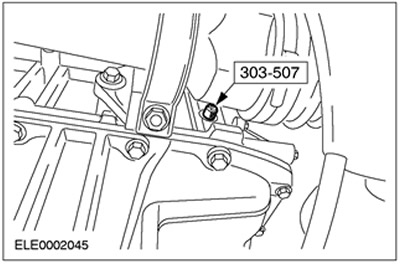
Turn the crankshaft to top dead center for cylinder #1.
- Remove the plug and screw in the special tool.
- Carefully turn the crankshaft clockwise until it rests against the special tool.
Timing Belt Tensioner with Cam
8.
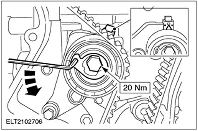
NOTE: Do not move the eccentric when tightening. Hold it using a socket wrench.
Tighten the timing belt (shown with engine removed).
- Using a 6mm socket wrench, turn the eccentric counterclockwise until the pointer arrow is exactly in the center of the rectangular hole.
- Tighten the bolt.
Timing Belt Tensioner with Groove
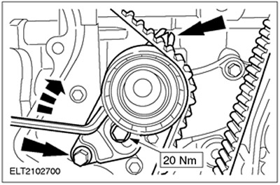
9. Tighten the timing belt (shown with the engine removed).
- Using a socket wrench, turn the tensioner so that the arrow is precisely aligned with the center of the rectangular hole.
- Tighten the bolts.
10.
CAUTION: Do not tighten the camshaft pulley while holding the camshaft from turning with Special Tool 303-376.
NOTE: Do not rotate the crankshaft or camshafts.
Tighten the bolts on the camshaft pulleys.
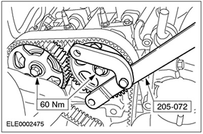
11. Remove special tool 303-376.
12. Unscrew the special tool (shown from below).
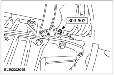
13. Check the valve timing.
- Turn the crankshaft two revolutions clockwise and bring cylinder No.1 to the top dead center position.
NOTE: If Special Tool 303-507 cannot be installed, turn the crankshaft back counterclockwise approximately 20 degrees.
- Screw in special tool 303-507.
- Carefully turn the crankshaft clockwise until it rests against special tool 303-507.
14. Check the valve timing by installing a special tool.
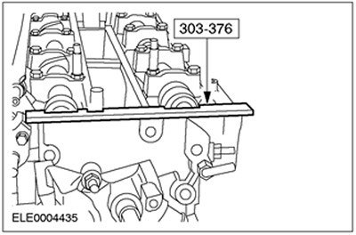
15.
NOTE: Only if special tool 303-376 cannot be inserted.
NOTE: Hold using special tool.
NOTE: The crankshaft must remain at top dead center for cylinder #1.
Adjust the valve timing.
- Loosen the bolt of the camshaft in question.
- Turn the camshaft by the hexagon until special tool 303-276 can be inserted.
- Tighten the pulley onto the camshaft.
- Check the valve timing again as described earlier.
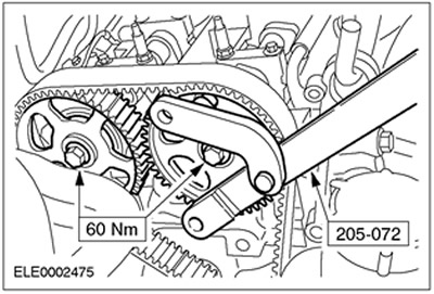
16. Install the spark plugs, use a special tool. Apply grease to the spark plug threads.
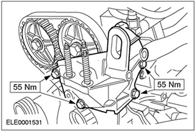
17. Install the front engine mount bracket.
18. Reinstall the upper timing belt cover.
19. Install the engine support.
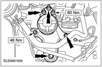
20. Remove the trolley jack.
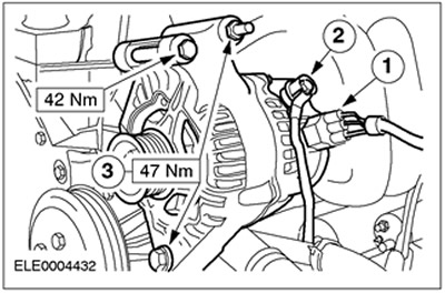
21. Install the generator.
- 1.Connect the connector.
- 2.Connect the positive wire.
- Install the studs.
- 3.Install the generator.
22. Raise the vehicle. Refer to Section 100-02 for additional information.
23. Unscrew special tool 303-507 and screw in the plug.
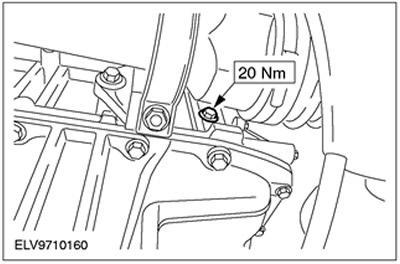
24. Install the upper timing belt cover bolts.
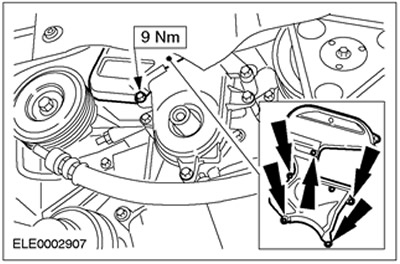
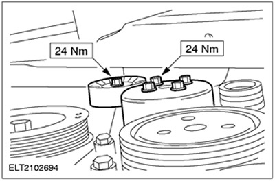
25. Install the coolant pump pulley and the drive belt idler pulley.
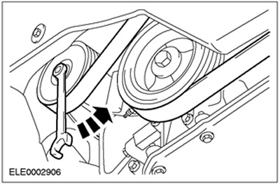
26. Install and tighten the drive belt.
27. Install the drive belt cover.
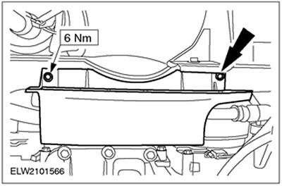
28. Lower the vehicle.
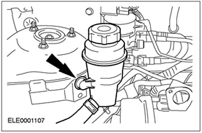
29. Secure the power steering fluid reservoir.
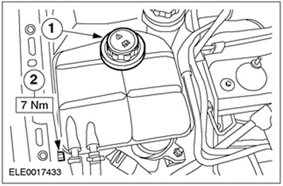
30. Connect the expansion tank of the cooling system.
- 1. Fix the expansion tank.
- 2. Tighten the bolt.
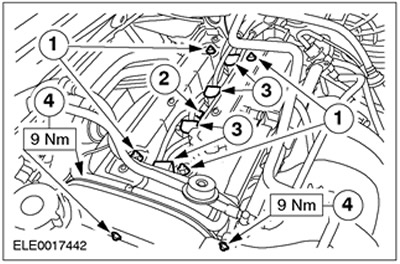
31.
CAUTION: To avoid damaging the spark plug connector seal, use a blunt object (such as a plastic zip tie) to apply silicone grease.
CAUTION: Connect the spark plug connector by applying a straight force to it.
NOTE: Coat the inside of the spark plug connector with silicone grease to a depth of (5-10) mm.
Install the cylinder head cover.
- 1. Install the nuts and tighten in two stages. Stage 1: 3 Nm. Stage 2: 10 Nm.
- 2. Connect the plug connector of the SNT sensor.
- 3. Connect the spark plug connector.
- 4.Install the three timing belt upper cover bolts.
32. Install the cylinder head cover plate (if removed).
- 1. Screw in the bolts (six bolts).
- 2.Connect the PCV hose.
- 3. Fix the bracket of the vacuum line of the carbon filter.
- 4. Secure the fuel lines.
33. Standard finishing operations:
- Connect the ground cable to the battery. Refer to Section 414-01 for additional information.
- If necessary, secure the wires using cable ties.
The original source of this article can be found at: FORDBOOK