Special tool
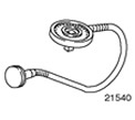 | Goniometer 303-174 (21540) |
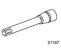 | Socket wrench for cylinder head bolts 303-392 (21167) |
General equipment: Rolling jack.
| Name | Specification |
| Coolant | WSS-M97B44-D |
| Lubricant for spark plugs («Never Seeze») | ESE-M1244-A |
| Sealant for junction of camshaft bearing caps with cylinder head | WSK-M2G348-A2 |
| Engine oil | WSS-M2C912-A1 |
Withdrawal
1. Standard preparatory activities:
- Use special tool 303-397 to install and remove coolant hoses and vent hoses, if necessary.
- Open the expansion tank of the cooling system.
2. Relieve pressure in the fuel system. See Section 310-00 for more information.
3. Disconnect a wire of weight from the accumulator. See Section 414-01 for more information.
4.
NOTE: Collect coolant and reuse if necessary.
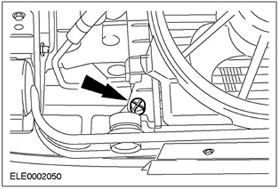
Drain the coolant (shown from below).
- Unscrew and remove the drain plug.
- Replace the drain plug after draining.
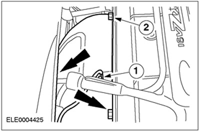
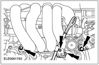
5. Remove the engine ground cable and exhaust manifold heat shield.
- 1. Engine ground cable
- 2.Exhaust manifold heat shield (three bolts)
6. Disconnect the exhaust manifold (shown from below) and tie it in place Remove the gasket.
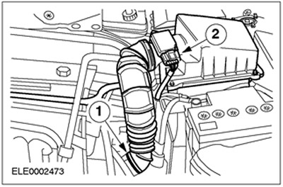
7. Remove the air filter and inlet hose.
- 1. Air intake hose.
- 2. Disconnect the plug connector of the mass air flow sensor (MAF).
- Disconnect the crankcase ventilation hose from the cylinder head.

8. Disconnect the accelerator cable.
- 1.Release the clip.
- 2.Unscrew the cable from the bracket.

9. Disconnect the crankcase ventilation hose.

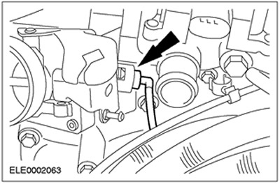
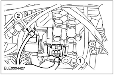
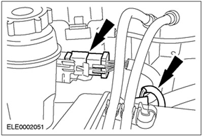
10. Disconnect the plug connector of the engine wiring harness and the plug connector of the camshaft position sensor (SMR).

11. Disconnect the connector.
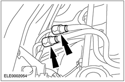
- 1.Ignition coil (EI)
- 2.Condenser

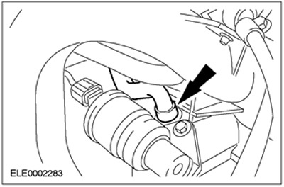
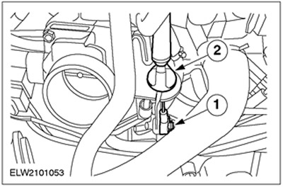
12. Disconnect the hoses and release the plug connector.
- 1.Vacuum hose of carbon filter solenoid valve
- 2.Knock sensor connector (KS)
- 3.Vacuum hose for brake booster

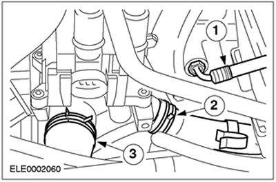
13. Remove the coolant and heater hoses.
- 1.Coolant bottle hose
- 2.Heater hose
- 3.Coolant hose
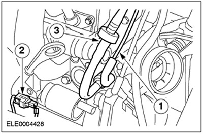
14. Disconnect the carbon filter vacuum line.
15.
WARNING: Fuel leakage. Observe fuel handling precautions.
NOTE: Fuel supply nipples are painted white or identified by a white ring. Fuel return nipples are colored red or identified by a red ring.
Disconnect the fuel lines.
16. Remove camshafts. For more information, refer to the chapter Camshafts available in this section.
17. Remove the three lower intake manifold bolts from the cylinder block and disconnect the oil level indicator tube. Disconnect the knock sensor connector (KS sensor) from the clamp on the oil dipstick tube.
18.
CAUTION: Allow the cylinder head to cool below 30°C before detaching it.
CAUTION: Place the cylinder head on a soft support surface.
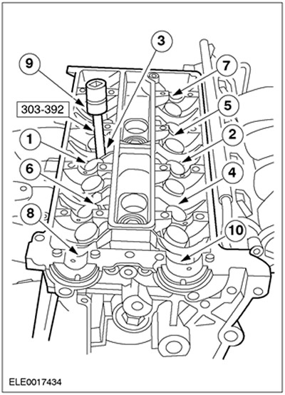
NOTE: Release sequence.
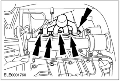
Disconnect the cylinder head. Turn out bolts of a head of cylinders. Use a special tool.
Installation
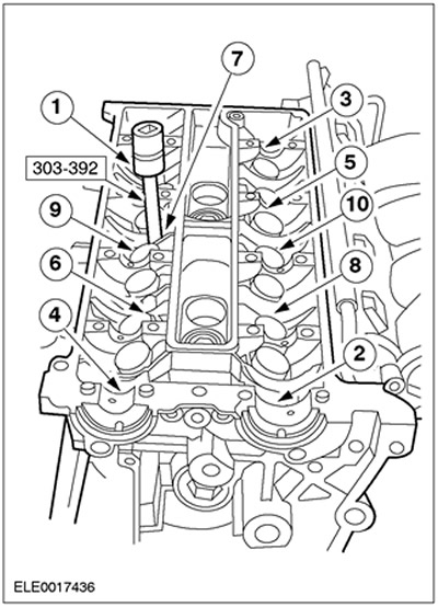
1.
NOTE: Tightening sequence.
NOTE: The cylinder head is mounted on two guide bushings.
NOTE: Cylinder head bolts are reusable.
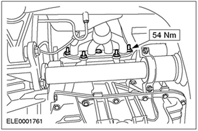
Install the cylinder head.
- Make sure all mating surfaces are clean.
- Install a new cylinder head gasket.
- Install the cylinder head, working in four steps in the sequence shown.
- Stage 1: 15 Nm
- Stage 2: 30 Nm
- Stage 3 using special tool 303-174: 90 degrees
2. Install the three lower intake manifold bolts and connect the oil dipstick tube. Lock the knock sensor connector (KS) on the oil dipstick tube.
3. Connect the fuel lines.

4. Install camshafts. For more information, refer to the chapter Camshafts available in this section.
5. Connect the carbon filter vacuum line.

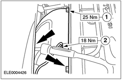
6. Connect coolant hoses and heater hoses. Use special tool 303-622.
- 1.Coolant bottle hose
- 2.Heater hose
- 3.Coolant hose

7. Connect the hoses and dock the connector.
- 1.Vacuum hose of carbon filter solenoid valve
- 2.Knock sensor connector (KS)
- 3.Vacuum hose for brake booster
8. Dock the connector.
- 1.Ignition coil (EI)
- 2.Condenser
9. Connect the plug connector of the engine wiring harness and the plug connector of the camshaft position sensor (SMR).
10. Connect the PCV hose.
11. Connect the accelerator cable.
- 1.Fix the clamp.
- 2.Fix the cable in the bracket.
12. Install the air filter along with the intake hose.
- 1.Air intake hose
- 2. MAF sensor connector (MAF)
- Connect the crankcase ventilation hose to the cylinder head cover.
13.
NOTE: Use a new exhaust manifold gasket.
Connect the exhaust manifold (shown from below).
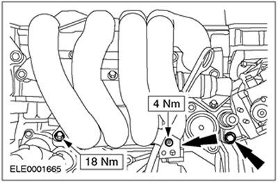
14. Connect the exhaust manifold heat shield and engine ground cable.
- 1.Exhaust manifold heat shield (three bolts)
- 2. Engine ground cable
15. Standard final operations:
- change oil (and oil filter).
- Connect ground wire to battery. See Section 414-01 for more information.
- Add working fluid to the cooling system. See Section 303-03 for more information.
- Remove air from the fuel supply system.
- Check engine and cooling system for leaks (visual inspection).
Visitor comments