Special tool
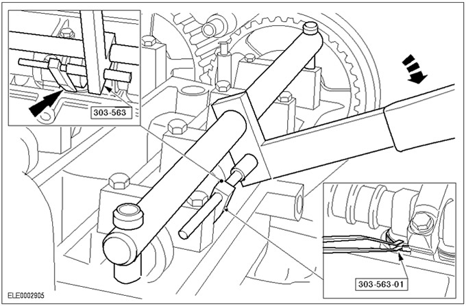
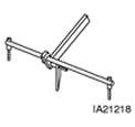 | Valve lifter compression tool 303-563 (21218) |
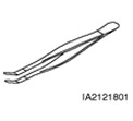 | Valve shim remover/installer 303-563-01 (2121801) |
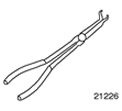 | Pliers for spark plug connectors 303-622 (21226) |
General equipment:
- Probe set
- Micrometer
| Name | Specification |
| Silicone Grease | A960-M1S171-AA |
Adjustment
1. Disconnect a wire of weight from the accumulator. See Section 414-01 for more information.
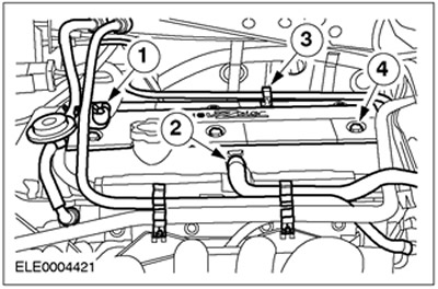
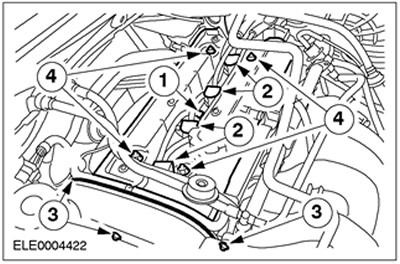
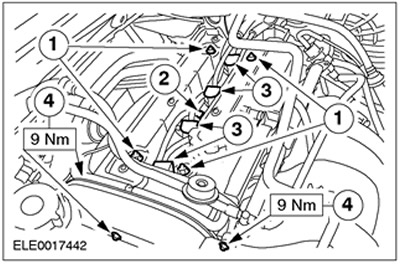
2. Remove the cylinder head cover.
- 1. Release the fuel lines.
- 2.Disconnect the crankcase ventilation hose.
- 3. Release the carbon filter vacuum line bracket.
- 4.Remove the bolts (six bolts).
3.
CAUTION: When disconnecting the spark plug connector, do not pull on the wire. If necessary, remove the ignition coil to avoid bending the wire. To release the gasket, turn the spark plug connector slightly before removing.
CAUTION: Disconnect the spark plug connector using straight line force only.
CAUTION: Do not damage the cylinder head cover gasket as it cannot be replaced individually.
Remove the cylinder head cover by moving it straight up.
- 1. Disconnect the plug connector of the cylinder head temperature sensor (SNT).
- 2. Disconnect the high voltage wires from the spark plugs.
- For angled spark plug connectors, use special tool 303-622.
- 3. Turn out three bolts from the top cover of a timing belt.
- 4. Loosen and remove the nuts.
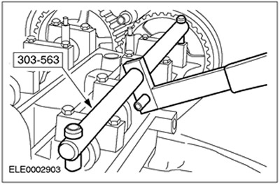
4.
NOTE: Install the long bolts from the front.
Connect the special tool.
- Remove the outer bolts from the first and last camshaft bearing caps.
- Install the special tool so that the compression tool guide faces out.
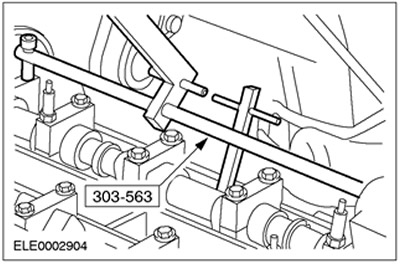
5.
NOTE: The cam of the valve in question must face up.
Connect the special tool. Insert the compression tool into the lever.
6. Determine the valve clearance in the valves of the first cylinder.
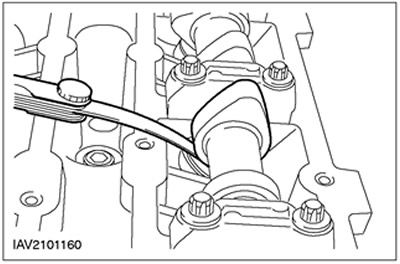
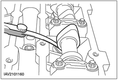
8.
NOTE: The tappet groove must face the center of the engine.
NOTE: Do not press down on the shim with a compression tool.
Remove the adjusting shim.
- 1. Attach a compression tool to the end of the valve lifter and push down on the lifter.
- 2.Remove the shim.
9. Determine the thickness of the shim with a micrometer.
10. Select a new shim. Determine the thickness of the new shim: Shim thickness (new) defined as measured valve clearance plus thickness "old" adjusting pad. The thickness of the selected new shim should differ from the calculated value by no more than 0.03 mm.
11. Insert a new valve shim having the thickness calculated in accordance with the previous paragraph.
12. Check the valve clearance; if necessary, adjust the valve clearance in accordance with the above points.
13. Perform these steps on each cylinder on the intake and exhaust sides, respectively.
14. Disconnect the special tool.

15.
CAUTION: To avoid damage to the spark plug connector seal, use a blunt object to apply silicone grease (e.g. plastic clamp).
CAUTION: Attach the spark plug connector using a straight line force.
NOTE: Coat the inside of the spark plug connector with silicone grease to a depth of (5-10) mm.
Install the cylinder head cover.
- 1.Install the nuts and tighten them, working in two stages. Stage 1: 3 Nm. Stage 2: 10 Nm
- 2. Connect the plug connector of the SNT sensor.
- 3. Connect the spark plug connector.
- 4.Install the three bolts of the upper timing belt cover.
16. Establish a cover on a cover of a head of cylinders.
- 1. Screw in the bolts (six bolts).
- 2. Connect the PCV hose.
- 3.Lock the carbon filter vacuum line holder.
- 4.Fix the fuel lines.

17. Standard final operations:
- Connect ground wire to battery. See Section 414-01 for more information.
- If necessary, secure the wires using cable ties.
- Check fluid levels and correct if necessary.
Visitor comments