Removal, check and installation
1. Remove valve cover (section 3).
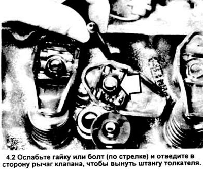
2. Loosen the valve lever pivot pin bolt so that you can turn the valve lever to one side and pull out the valve lifter rod (see picture).
3. If you are removing more than one rod, install them so that they can later be installed exactly in the field.
4. If you are going to remove all valve levers, mark them as such. so that you can then install in places - do not confuse.
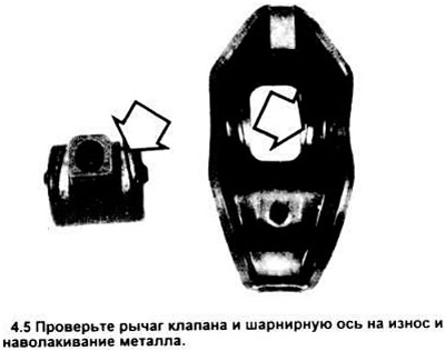
5. Clean all parts and check for wear and damage. The push rods can be rolled on the glass to check their straightness. Check hinge pins and levers for wear and metal enveloping. Wear out most often the contact points of the rods and levers (see picture). If wear is obvious, replace the part.
6. Before installing, apply lubricant based on "moth" or engine oil on the hinge pins and the ends of the push rods.
7. Make sure the valve lifter is lowered before installing the push rod. If necessary, turn the crankshaft with a wrench to lower the valve lifter.
8. Tighten the valve lever bolt to specification.
9. If any parts have been removed, check valve adjustment as described below.
10. Reinstall the cover (And) valve mechanism (section 3).
Adjustment
Note: Usually adjustment is only done if the"any parts/or if the seats and valves have been lapped.
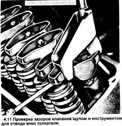
11. Using a Ford tool for pulling down the pusher type T70P - 6513 - A or similar (see picture), push the valve lever until the tappet slides down. Check the clearance between the valve stem and its lever with a feeler gauge. Compare with the specification and note the value. Repeat the operation for each of the valves in the order shown below.
Note: inlet location (I) and graduation (E) valves. starting from the front (from the drive belt), the following:
Left-hand side (front)
3.0L - I - E - I - E - I - E
3.8L - E - I - E - I - E - I
Right side (rear)
3.0L - E - I - E - I - E - I
3.8L - I - E - I - E - I - E
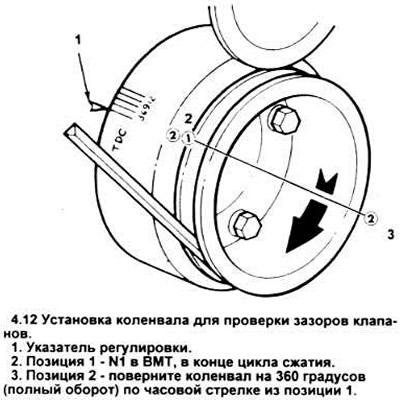
12. Set piston #1 to TDC on the compression stroke (section 11). This is position 1 (see picture).
13. Check the following valves:
inlet - 1, 3 and 6
release - 1, 2 and 4
14. Turn the crankshaft to position 2 and check the following valves:
inlet - 2, 4 and 5
release - 3, 5 and 6
If clearances are within specification, install valve cover.
15. If clearances are small, use shorter push rods; if too large - longer.
Visitor comments