Adjusting valve clearances
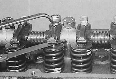
See. subsection 3.1.2.1 and subsection 3.2.3.1 taking into account the following additions.
From the thermostat side, the valves on OHV gasoline engines are arranged as follows.
| Valve | Cylinder | |
| 1 | Outlet | 1 |
| 2 | Inlet 1 | 1 |
| 3 | Outlet | 2 |
| 4 | Inlet 2 | 2 |
| 5 | Outlet | 3 |
| 6 | Inlet 3 | 3 |
| 7 | Outlet | 4 |
| 8 | Inlet 4 | 4 |
Turning the bolt clockwise decreases the valve clearance, and counterclockwise increases it.
[Content was created using data from this website Fordbook.ru]