Electrical equipment and appliances Ford Escort 4

Technical characteristics of electrical equipment
Nominal voltage is 12 volts, the "minus" is connected to the "ground" of the car. Battery capacity is 35-50 Ah. Generator An alternator from Bosch, Lucas or Motorola is...
Nominal voltage is 12 volts, the "minus" is connected to the "ground" of the car. Battery capacity is 35-50 Ah. Generator An alternator from Bosch, Lucas or Motorola is...
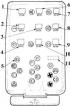
Fuses and relays
Relay block installed until the end of 1985 1, 3 – spare fuses; 2 – ignition relay; 4 – relay for periodic switching on of windshield wipers; 5 – power supply relay for...
Relay block installed until the end of 1985 1, 3 – spare fuses; 2 – ignition relay; 4 – relay for periodic switching on of windshield wipers; 5 – power supply relay for...

Removing and installing the generator
Mounting of generators 1 – tension bar; 2 – V-belt; 3 – generator; 4 – generator mounting bracket; 5 – bracket; 6 – lid; 7 – oil protection Despite the differences in...
Mounting of generators 1 – tension bar; 2 – V-belt; 3 – generator; 4 – generator mounting bracket; 5 – bracket; 6 – lid; 7 – oil protection Despite the differences in...

Adjusting the V-belt tension
OHV Engine Alternator Belt Tension 1 – crankshaft pulley; 2 – water pump pulley; 3 – generator pulley CVH Engine Generator Belt Tension 1 – crankshaft pulley; 2 –...
OHV Engine Alternator Belt Tension 1 – crankshaft pulley; 2 – water pump pulley; 3 – generator pulley CVH Engine Generator Belt Tension 1 – crankshaft pulley; 2 –...

Replacing the generator brushes and voltage regulator Bosch
Bosch Generator 1– fan pulley; 2 – front cover; 3 – rotor; 4 – bearing; 5 – stator; 6 – rectifier; 7 – back cover; 8 – brush holder; 9 – electronic voltage regulator The...
Bosch Generator 1– fan pulley; 2 – front cover; 3 – rotor; 4 – bearing; 5 – stator; 6 – rectifier; 7 – back cover; 8 – brush holder; 9 – electronic voltage regulator The...

Replacing the Generator Brushes and Voltage Regulator Lucas
Lucas Generator 1– fan pulley; 2 – front cover; 3 – rotor; 4 – bearing; 5 – stator; 6 – rectifier; 7 – back cover; 8 – brush holder; 9 – electronic voltage regulator The...
Lucas Generator 1– fan pulley; 2 – front cover; 3 – rotor; 4 – bearing; 5 – stator; 6 – rectifier; 7 – back cover; 8 – brush holder; 9 – electronic voltage regulator The...

Motorola Generator and Voltage Regulator Brush Replacement
Motorola Generator 1– fan pulley; 2 – front cover; 3 – rotor; 4 – bearing; 5 – stator; 6 – rectifier; 7 – back cover; 8 – brush holder; 9 – electronic voltage regulator...
Motorola Generator 1– fan pulley; 2 – front cover; 3 – rotor; 4 – bearing; 5 – stator; 6 – rectifier; 7 – back cover; 8 – brush holder; 9 – electronic voltage regulator...
Main generator faults
When checking the generator, as well as when operating the vehicle, it is necessary to follow a number of simple rules in order not to damage the generator: do not allow...
When checking the generator, as well as when operating the vehicle, it is necessary to follow a number of simple rules in order not to damage the generator: do not allow...

Features of the starter design
Bosch starter 1 – head; 2 – drive unit; 3 – drive lever; 4 – electromagnetic switch; 5 – stator; 6 – rotor; 7 – brush holder Lucas starter 1 – head; 2 – drive unit; 3 –...
Bosch starter 1 – head; 2 – drive unit; 3 – drive lever; 4 – electromagnetic switch; 5 – stator; 6 – rotor; 7 – brush holder Lucas starter 1 – head; 2 – drive unit; 3 –...

Removing and installing the starter
1. Disconnect the ground wire from the battery. 2. Raise the front of the vehicle and secure it on stands. 3. Unscrew the wires from the traction relay and mark them. 4....
1. Disconnect the ground wire from the battery. 2. Raise the front of the vehicle and secure it on stands. 3. Unscrew the wires from the traction relay and mark them. 4....
Main faults of the starter
CAUSE METHOD OF ELIMINATION When the starter is turned on, the starter motor does not work Starter or traction relay failure or defective wiring Check for voltage at...
CAUSE METHOD OF ELIMINATION When the starter is turned on, the starter motor does not work Starter or traction relay failure or defective wiring Check for voltage at...

Removing and installing the instrument cluster
Elements of the center console 1 – lever cuff; 2 – console for radio equipment; 3 – center console; 4 – console extension; 5 – cassette box; 6 – plug Back of instrument...
Elements of the center console 1 – lever cuff; 2 – console for radio equipment; 3 – center console; 4 – console extension; 5 – cassette box; 6 – plug Back of instrument...

Removal and installation of measuring instruments
Back of instrument cluster since 1986 1 – watch mount; 2 – speedometer mount; 3 – fastening of temperature and fuel gauges. The arrows show the screws connecting the...
Back of instrument cluster since 1986 1 – watch mount; 2 – speedometer mount; 3 – fastening of temperature and fuel gauges. The arrows show the screws connecting the...

Removing and installing switches
Removal of the three-stage heater switch on models up to the end of 1985 1 – switch handle; 2 – switch; 3 – spring clamps (compress towards the switch axis) Removing the...
Removal of the three-stage heater switch on models up to the end of 1985 1 – switch handle; 2 – switch; 3 – spring clamps (compress towards the switch axis) Removing the...

Removing and installing the brake light switch
1. Remove the left trim under the instrument panel by releasing the 3 clamps and pressing the metal fasteners. 2. Remove the connector from the switch, unscrew the lock...
1. Remove the left trim under the instrument panel by releasing the 3 clamps and pressing the metal fasteners. 2. Remove the connector from the switch, unscrew the lock...
This section is available on russian, bulgarian, belarusian, ukrainian, serbian, croatian, romanian, polish, slovak, hungarian
See other similar sections for Ford cars:
• General information: Vehicle device Ford Focus 2 (2004-2010)
• Electrical equipment: Equipment and devices Ford Mondeo 1 (1993-1996)
• Electrical equipment: Equipment and devices Ford Scorpio 1 (1985-1994)
• Electrical equipment: Equipment and devices Ford Transit 2 (1986-2000, diesel)
• General information: Vehicle device Ford Focus 2 (2004-2010)
• Electrical equipment: Equipment and devices Ford Mondeo 1 (1993-1996)
• Electrical equipment: Equipment and devices Ford Scorpio 1 (1985-1994)
• Electrical equipment: Equipment and devices Ford Transit 2 (1986-2000, diesel)
Escort 5
Escort 4
Escort 3
- General information
- User manual
- Maintenance
- Engine
- HCS and Endura-E engines
- CVH and PTE engines
- Zetec and Zetec-E engines
- Gasoline engines
- Diesel engines
- Diesel engines (since 1992)
- Cooling and heating
- Carburetors
- CFI fuel injection
- EFI fuel injection
- SEFI fuel injection
- Exhaust system
- Charging and starting system
- Ignition system
- Transmission
- Clutch
- Mechanical gearbox
- Automatic gearbox
- Drive shafts
- Chassis
- Brake system
- Car suspension
- Steering
- Body
- Electrical equipment
- Light and appliances
- Schematic diagrams
Escort 4
- General information
- User manual
- Maintenance
- Gasoline engines
- OHV engine repair
- CVH engine repair
- Fuel system
- Weber 2V carburetor
- KE-Jetronic injection system
- CFI injection system
- Ignition system
- Diesel engines
- Engine repair
- Fuel system
- High pressure pump
- Cooling and lubrication system
- Transmission
- Clutch
- Mechanical gearbox
- Automatic gearbox
- Drive shafts
- Chassis
- Suspension and wheels
- Steering
- Brake system
- Body
- Body elements
- Doors, locks and windows
- Electrical equipment
- Equipment and devices
- Lighting system
- Electrical circuits
Escort 3
- General information
- Maintenance
- Characteristics
- Engine
- Disassembly and assembly
- Cooling system
- Lubrication system
- Supply system
- Fuel injection «K-Jetronic»
- Transmission
- Clutch
- Mechanical gearbox
- Hydromechanical box
- Drive shafts
- Chassis
- Front suspension
- Rear suspension
- Steering
- Brake system
- Electrical equipment
- Starting and charging system
- Ignition system
- Ignition «Escort RS 1600»
- Light and appliances
- Schematic diagrams