Withdrawal
1. Loosen the toothed belt (1-14 paragraph 10).
2. Remove the belt completely (paragraph 10 paragraphs 15 and 16) or pull it off the camshaft pulleys without creating large kinks, working only with your fingers. Cover the belt and secure it away from the work area. Do not turn the crankshaft until the belt is installed.
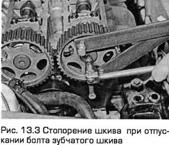
3. Turn out bolts of pulleys (see paragraph 10. paragraphs 18 and 21) and remove the pulleys. Since the pulleys are the same, in order not to confuse them during installation, it makes sense to mark them (see fig. 13.3).
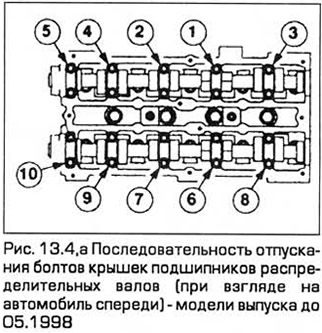
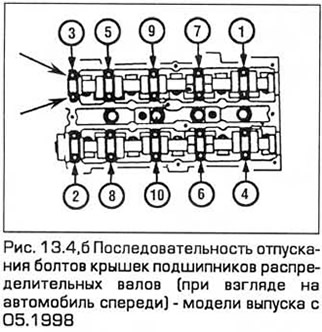
4. Acting sequentially and in a cross order, loosen the bolts of the camshaft bearing caps (loosening the bolt half a turn at a time) (see fig. 13.4, a, b). This is necessary for the gradual and uniform removal of force from the covers, which are pressed by the valve springs.
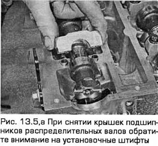
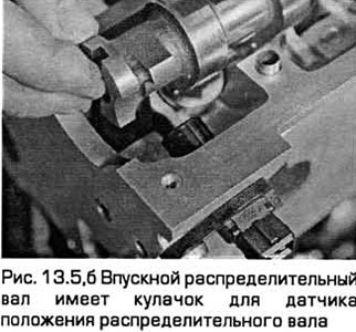
5. Remove the covers, taking into account their markings and paying attention to the locating pins. Then remove the camshafts and pull out their cuffs. The intake camshaft has a cam for the camshaft position sensor. In this it differs from the exhaust camshaft, and therefore it is not necessary to mark the shafts (see fig. 13.5, a, b).
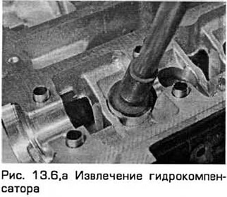
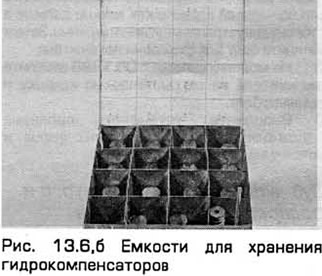
6. You will need 16 small containers, numbered 1 to 16. Remove the hydraulic lifters with a rubber suction cup. On models manufactured from 05.1998, keep the shims together with the corresponding expansion joints. On early production models, to prevent oil leakage, turn them over and lower them into appropriate containers to be filled with engine oil. Do not confuse hydraulic lifters with each other, as this can lead to significant wear. Do not allow oil to flow out of them, otherwise, when starting the engine, they will take a long time to fill, which causes a violation of valve clearances, (see fig. 13.6, a, b).
Inspection
7. After removing the camshafts and hydraulic lifters, inspect them for wear (scratches, pitting, etc.), as well as ovality. Replace defective parts if necessary.
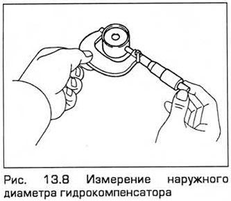
8. Measure the outer diameter of each hydraulic lifter (see fig. 13.8). Measure the diameter at the top and bottom of the hydraulic lifter, and then repeat the measurements in the perpendicular direction. If any of the dimensions obtained is significantly different from the rest, then the compensator has a taper or ovality, and it must be replaced. If you have the necessary equipment, measure the inner diameter of the corresponding hole in the block head. Compare the obtained dimensions with the technical requirements. If the lifters or bores are excessively worn, you will need new lifters and/or a new cylinder head.
9. If the valve mechanism knocks, and especially when starting a cold engine, then a faulty hydraulic compensator is probably the cause of this. Only an experienced auto mechanic who knows such engines can determine by ear whether such noise is normal or whether one or more hydraulic lifters need to be replaced. 8 case of looking for faulty hydraulic lifters, when you do not know what kind of maintenance the engine has previously undergone, it makes sense to try changing the engine oil and filter (see chapter 1) before purchasing new hydraulic lifters. See also information paragraph 1 this chapter and use only high quality engine oil of the specified viscosity and specification.
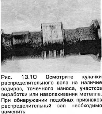
10. Inspect the camshaft lobes for nicks, pitting, pitting or pitting of metal, and hot spots (tint colors). Inspect for chipping of the hardened surface layer of each cam (see fig. 13.10). If these symptoms are found, the defective components must be replaced.
11. Inspect the camshaft bearing journals and head bearing surfaces for wear, particularly pitting. If any of these symptoms are found, replace the defective components.
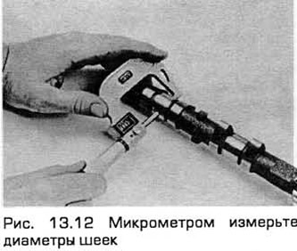
12. Using a micrometer, measure the diameters of the necks in several places (see fig. 13.12). If the diameter of one of the necks is less than indicated in Technical data, replace the camshaft.
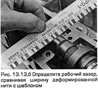
13. To check the operating clearance of the bearings, remove the compensators and thoroughly wash the bearing surfaces with a suitable solvent using a clean, lint-free cloth. Then install the camshafts and bearing caps, laying a piece of thread along the axis of the shaft on each neck "plastic probe" (see fig. 13.13, a). Tighten the bearing cap bolts to the required torque (without turning the camshafts). Then remove the covers and determine the gaps by checking the width of the deformed thread with the template (see fig. 13.13, b). Peel off the used filament with your fingernail or plastic scraper. Do not scratch the journals or bearing caps.

14. If the operating clearance in one of the bearings is outside the limits specified in the Technical data, install a new camshaft and repeat the test. If you find excessive clearances, then the block head needs to be replaced.
15. To check the axial play of the camshaft, remove the hydraulic lifters, thoroughly clean the surfaces of the bearings and install the camshafts and bearing caps. Tighten the bearing cap bolts to the specified torque. Then measure the end play with a dial indicator. To do this, install it on the head of the block so that the tip of the indicator rests on the right end of the camshaft.
16. Press the camshaft against the indicator, reset the indicator, and then press the camshaft away from the indicator and take readings. If the result obtained corresponds to the maximum backlash or exceeds it (see technical data), install a new camshaft and recheck. If in this case the play remains excessive, then the block head must be replaced.
Installation
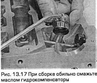
17. When assembling, generously lubricate the hydraulic lifters and the holes for them in the block head with oil (see fig. 13.17). In the case of installing new hydraulic lifters, they must first be filled with oil. Carefully install the hydraulic lifters in the head of the block - in their places, with the corresponding side, Insert the hydraulic lifters into the holes without distortions.
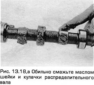
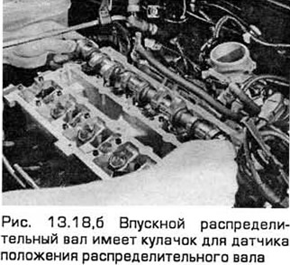
18. Copiously lubricate the bearing journals and camshaft lobes with oil. Install the camshafts in their places so that the slot on the left end of each shaft is parallel and slightly above the joint surface of the head of the block with the cover (see fig. 13.18, a, b).
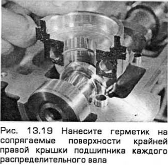
19. Make sure all dowel pins are firmly driven in and all mating surfaces are clean and free of oil. Apply a thin layer of an appropriate sealant (Ford recommends Loctite 518 sealant) on the mating surfaces of the rightmost bearing cap of each camshaft (see fig. 13.19). In this case, you can install new cuffs camshafts (see point 6 paragraph 12).
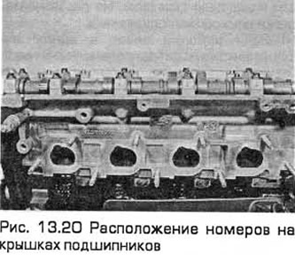
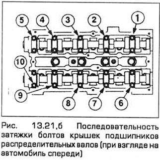
20. Each bearing cap is etched with a number to identify it (see fig. 13.20). The exhaust camshaft bearing caps are numbered from 0 (extreme right cover) up to 4 (far left cover), and intake shaft covers - from 5 (extreme right cover) up to 9 (far left cover) (see fig. 13.21, b). The cover must be installed so that the surface with the number is directed outward, forward (for exhaust shaft) or back (for intake shaft).
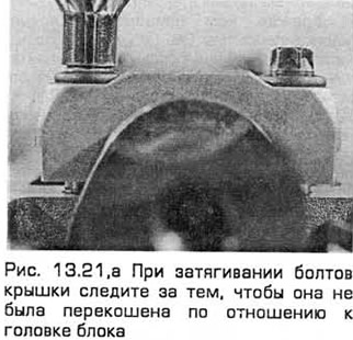
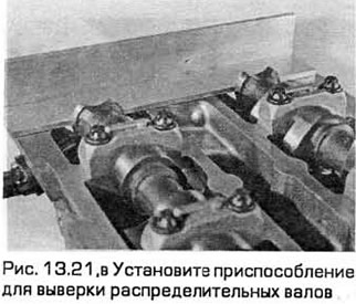
21. Be careful when tightening the cover bolts. so that it is not skewed in relation to the block head. Tighten the caps in a criss-cross pattern one turn at a time for each bolt until all caps touch the head of the block (see fig. rice. 13.21, a, b). After that, tighten the bolts in the same sequence to the required torque in the first stage, and then in the second stage. This is necessary for the gradual and uniform loading of the covers by the force of the valve springs. Install the camshaft alignment tool. He must be in the position described in clause 10 of paragraph 10 (see fig. 13.21, in).
22. Wipe off the remains of the sealant so that it does not get into the oil channels. Follow the instructions for use of the sealant. Usually, after applying the sealant, you need to wait a while (at least an hour) before starting the engine.
23. If you are following Ford's recommended procedures, install new camshaft seals as directed in paragraph 5 of paragraph 12.
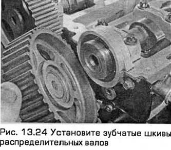
24. According to the marks made during removal, install the camshaft pulleys in their places, slightly tightening their bolts (see fig. 13.24). Pull the belt over the pulleys (21 paragraph 10) and securely tighten the bolts with a scissor type tool (18 paragraph 10).
25. Other installation operations, including alignment of the position of the camshafts (gas distribution mechanism) and restoring the tension of the toothed belt, perform as indicated in paragraph. 17-27 paragraph 10. On models from 05.1998, check and adjust valve clearances (see paragraph 14).
Visitor comments