Warning: This procedure must be performed when the engine is completely cold.
Note: In addition to a new gasket and other parts, tools and fixtures required for this job, you will need a new plastic guide bushing for installation.
Withdrawal
1. Disconnect the negative battery cable (chapter 5, paragraph 1).
2. Turn out bolts of fastening of an arm of a support of the resonator from a forward cross-member of engine compartment. Loosen the two screws of the clamps that secure the resonator to the hoses of the air flow meter and prechamber. Then move the resonator away from the thermostat housing (chapter 4).
3. Empty the cooling system (Chapter 1).
4. Disconnect the coolant hose and coolant line/hose from the thermostat housing. Fix them away from the work area.
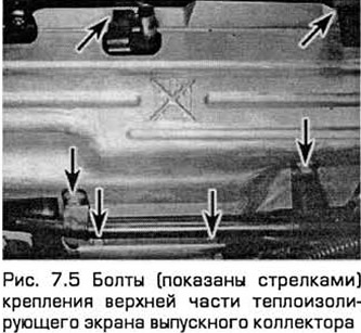
5. Turn out bolts of the heat-insulating casing of a final collector and remove both parts of a casing (see fig. 7.5). When loosening the RVG pipe nuts, exhaust manifold support nuts, and afterburner system nuts, use penetrating oil.
6. Turn away a nut of fastening of the pipeline of RVG system to a collector. Remove the two screws securing the piping to the ignition coil bracket. Then loosen the nut securing the pipeline to the valve of the RVG system (chapter 6).
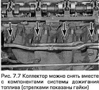
7. The manifold can be removed along with the components of the afterburning system. To do this, unscrew the filter housing mounting bolts and disconnect its vacuum hose. But still, it is easier to first remove the afterburner assembly (chapter 46, see fig. 7.7).
8. Disconnect the oxygen sensor wiring harness connector so as not to strain its wiring. Loosen the nuts to disconnect the exhaust pipe from the manifold (Chapter 4).
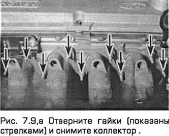
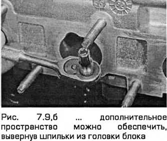
9. Remove nuts and remove manifold and gasket (see fig. 7.9, a). When pulling the manifold out of the engine compartment, be careful not to damage adjacent components such as the EGR system piping. If you are removing the manifold from an engine installed in a vehicle, additional space can be provided by removing the studs from the head of the block. This will require a head with slots inside it (see fig. 7.9, 6).
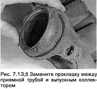
10. When installing, always install a new gasket on thoroughly cleaned components (see below). Do not attempt to use a used gasket.
Inspection
11. Use a scraper to remove the remnants of the old gasket, as well as carbon deposits from the mating surfaces of the manifold and block head. If the gasket is leaking, have the manifold inspected by a bodyshop for buckling and, if necessary, have it reworked on that surface.
Attention: When scraping, do not scratch the block head, which is made of aluminum
12. Provided the mating surfaces are clean and level, a new gasket will provide a gas-tight joint. Do not use sealants in areas upstream of the catalytic converter (in the direction of flow).
13. Note that the downpipe is attached to the exhaust manifold with two bolts, each with a helical spring, a spring seat and a self-locking nut. When installing, tighten the nuts until they rest against the shoulders of the bolts. This creates a spring force that prevents leakage through the joint (see fig. 7.13, a, b).
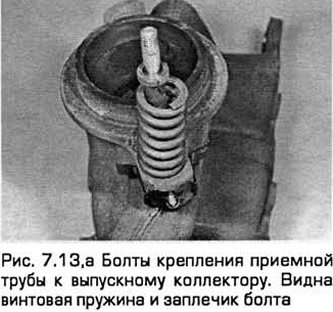
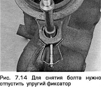
14. Do not overtighten nuts to stop leaks. If leaks are found, replace the gasket and spring. Bolts are fixed on the collector with elastic clamps. Bolts can be easily replaced if damaged (see fig. 7.14).
Installation
15. Installation - in the reverse order of removal, taking into account the following:
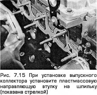
- A) Install a new gasket on the head studs. Install the new plastic guide bushing onto the stud closest to the thermostat housing (see fig. 7.15). Do not install manifold without this bushing.
- b) Install the manifold and hand-tighten its support nuts.
- V) Starting from the middle, tighten the nuts to the required torque (in three or four stages - see Technical Requirements).
- G) Install the rest of the parts in the reverse order of removal. Tighten all fasteners to the required torque.
- d) Recharge the cooling system (Chapter 1).
- e) Start the engine and check for leaks in the exhaust system. After the engine has warmed up to normal operating temperature, check the coolant level.
Visitor comments