Note: You will need a new belt to complete this procedure (of necessity), new cylinder head gasket and special tools (see text). If on models prior to 05.1998 the belt is removed for the first time since the vehicle left the factory, then purchase a tensioner spring and locking pin to install them during assembly.
Withdrawal
1. Disconnect the negative battery cable (chapter 5, paragraph 1). Apply the parking brake, raise the front of the vehicle and support it on stands. Remove the right front wheel and locker from under the right fender. The components of the timing belt transmission for models manufactured before 05.1998 are shown in fig. 10.1.
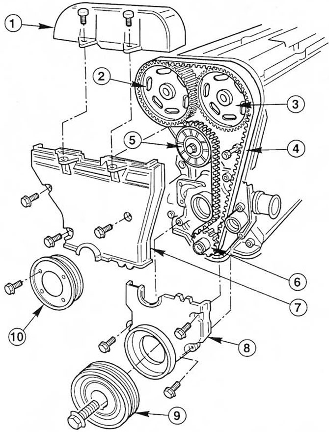 Pic. 10.1 Timing mechanism drive parts
1. Upper belt drive cover
2. Intake camshaft sprocket
3. Exhaust camshaft sprocket
4. Timing belt of the timing mechanism
5. Toothed belt tensioner
6. Crankshaft pulley
7. Middle toothed belt cover
8. Timing belt bottom cover
9. Crankshaft pulley for driving accessories
10. Coolant pump pulley
2. Remove the steering injection pipe bolts that secure it to the engine lifting eye/rear head base plate and to the pump bracket/front base plate.
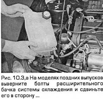
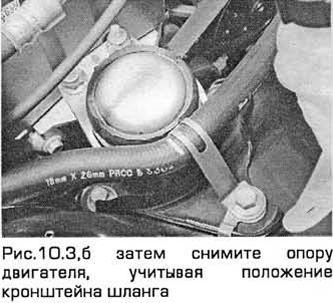
3. Turn away six nuts of fastening of an arm of the right support of the engine/transmission, and then remove an arm. On models of late releases turn out bolts of a broad tank of the cooling system and move it aside without disconnecting hoses. One of the engine mount bolts also secures the hose bracket (see fig. 10.Z, a, b).
4. Loosen the coolant pump pulley bolts.
5. Remove the head cover (section 5) (see fig. 10.5).
6. Remove the spark plugs. Plug their holes with clean rags to keep dirt out (Chapter 1).
7. Remove the accessory drive belt (Chapter 1).
8. Turn the crankshaft clockwise so that the second pair of notches on the pulley rim is aligned with the edge of the sump mark. In this case, cylinders No. 1 and 4 must be at TDC (paragraph 4).
9. Turn out bolts and remove a pulley of the pump of the cooling system and parasitic pulley of a belt of a drive of auxiliary units.
10. Get a special tool (Ford 21-162) or make your own. This should be a corner whose buttocks are 5 mm thick, 20-30 mm wide and 180-230 mm long (the thickness of the plate is important, and the width and length are approximately). Make sure cylinders #1 and #4 are at TDC. cylinder #1 on the compression stroke. To do this, install the above device on the surface of the block head, which is joined with its cover, and slide the device into the slots of both camshafts located on their left ends (see fig. 10.10). The device should fit snugly, but without difficulty, into both slots, adjoining the joint surface of the block head. If one of the camshafts is slightly offset from this position, then it is allowed to gently turn the camshaft with a wrench until it is aligned with the fixture.
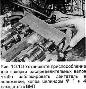
11. If the slots of both camshafts (which are made below the axes of the shafts) are located below the level of the joint surface of the head of the block, turn the crankshaft one full turn clockwise. And then install the stopper again. Now it should fit into the slots (see point 10).
12. Keeping the stopper in this position, remove the crankshaft pulley. To prevent it from turning, do not lock the camshafts. To do this, proceed as described in paragraph 8.
13. Remove the bottom and middle timing belt covers (paragraph 9).
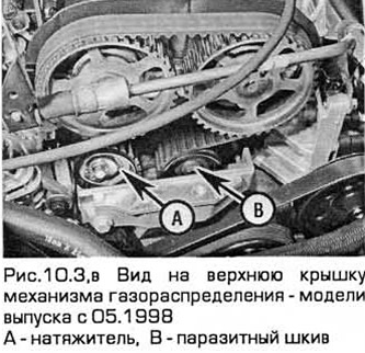
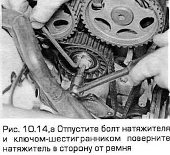
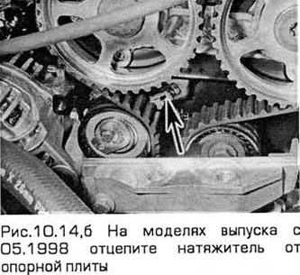
14. Maintaining the position of the locking device, release the tensioner bolt and, inserting the hex wrench into its center, turn the tensioner clockwise (release models before 10.1996) or counterclockwise (release models from 10.1996 to 05.1998) as far away from the belt as possible. Re-tighten the bolt to secure the tensioner away from the belt (see fig. 10.14, a, b). On production models from 05.1998, unscrew the tensioner bolt 4 turns and remove the tensioner from the base plate.
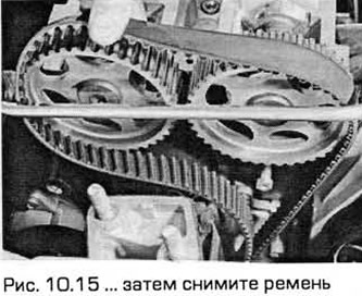
15. If the toothed belt is to be used again, then with white paint (or something similar) mark the direction of rotation of the belt, and also note which side it is installed, paying attention to the manufacturer's markings. Remove the belt (see fig. 10.15). Do not turn the crankshaft until the belt is back in place.
16. If you removed the belt not for a planned replacement, but for other reasons, carefully inspect it for uneven wear, cracks (especially at the base of the teeth) or oil or coolant contamination. If you doubt the serviceability of the belt, be sure to replace it. For safety reasons, the belt must be replaced according to the schedule (Chapter 1). If you do not know in what conditions the belt worked, then it must be replaced regardless of its condition during engine repair. Check the tensioner spring in the same way (if available) and replace if in doubt. Also check the toothed pulleys for wear or damage. Check that the idler pulleys and tensioner pulley rotate smoothly in their bearings. Replace worn or damaged components. If oil or coolant contamination is found, identify the source of the leak and repair it. Then wash the surface of the engine and components in the belt area to remove traces of oil or coolant.
Installation and adjustment
17. When installing, temporarily fit the crankshaft pulley to check the alignment of the pulley marks and the pallet mark (as indicated in paragraph 8). Then, using a locking device, check the installation of the camshafts in the position corresponding to TDC (item 10). If you are reassembling the engine after its general disassembly, then the pulleys of both camshafts must rotate freely relative to the shafts. If you are only replacing the belt, then both pulleys must be fixed to the shafts during the procedure.
18. To prevent the camshaft pulleys from turning when loosening and tightening their bolts, you will need a special tool. It could be a brand name (Ford 15-030 A) or homemade. For its manufacture, you will need two steel strips 600 and 200 mm long and three bolts with nuts and washers (see fig. 10.25). The ends of the bars are connected by a hinge (bolt. nut and washer), and a bolt, nut and washer is also installed on each of the remaining ends of the slats.
Note: Do not use the tool used to set the TDC to lock the camshafts because of the risk of damage to the corresponding camshaft and block head. Use only a scissor-type tool and mount it directly on the pulleys.
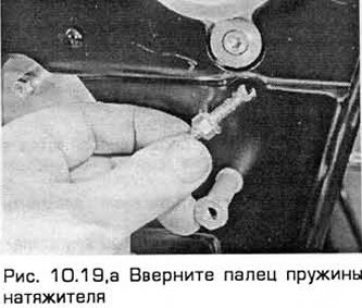
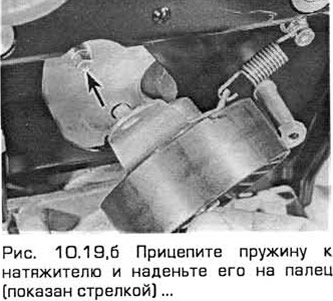
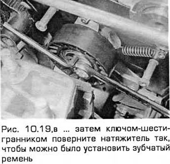
19. If installing the belt for the first time (on models before 05.1998), screw the toothed belt tensioner spring lock pin into the block head and tighten it to the required torque. Turn out a bolt of a tensioner, put on a spring on a finger and a back cover of a tensioner. Then install the tensioner, aligning its rear cover with the mounting lug (see fig. 10.19, a-c). In any case, loosen the tensioner bolt (if necessary) and with a hex wrench inserted in its center, turn the tensioner clockwise as far as possible, loosening the spring tension. Then re-tighten the bolt to secure the tensioner.
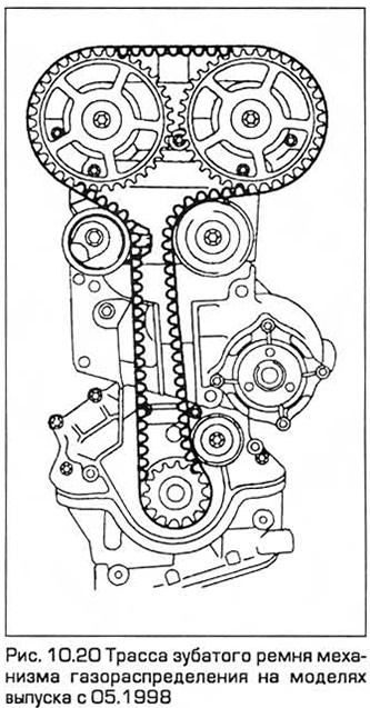
20. On production models from 05.1998, the tensioner has a different device. The tensioner spring is not used. When installing the belt, the tensioner bracket does not need to be put on the base plate until then. until the belt is installed on the pulleys (see fig. 10.20).
21. Install the toothed belt. If you install the removed belt again, then you need to install it with the same side so that it rotates in the same direction. Start installing the belt at the crankshaft pulley, continue in a counter-clockwise direction, sliding it over the camshaft pulleys and tensioner, and finally, put the belt on the rear idler pulley. The front branch between the gear pulleys of the crankshaft and the exhaust camshaft must be kept in tension without changing the position of the crankshaft and camshafts. If necessary, the position of the camshaft pulleys can be changed by turning each pulley on the shaft (which at this time is fixed by a locking device to align the timing marks). If the pulley is attached to the shaft, use the tool described in step 18 to keep the pulley from turning while loosening its mounting bolt. After that, the pulley can be rotated on the shaft until the belt settles into place. Then tighten the pulley bolt again.
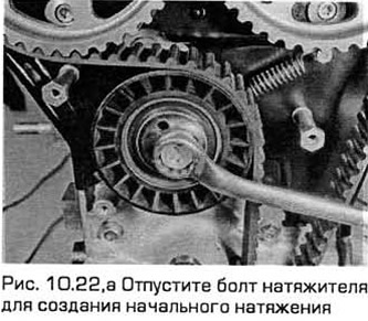
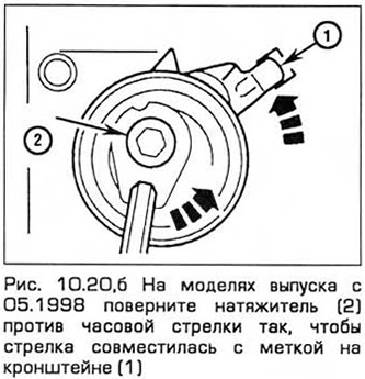
22. On production models before 05.1998, after installing the belt in place, carefully release the tensioner bolt so that it is again attracted by the spring to the belt. The tensioner must remain in position, adjacent to the inner casing of the toothed belt and the head of the block, and at the same time move to maintain belt tension (see fig. 10.22, a). On production models from 05.1998, put the tensioner on the base plate and insert the bolt, turning it slightly (about 4 turns). Turn the tensioner with the wrench. so that the arrow aligns with the mark or square hole in the bracket. Then tighten the center bolt (see fig. 10.22, b).
23. Tighten the bolts of both camshaft pulleys (or check their tightening). Remove the alignment tool. Temporarily install the crankshaft pulley and rotate this shaft two turns clockwise to settle and tension the belt, returning the crankshaft (according to the pulley marks) to the position described in step 8. Install the camshaft alignment tool according to step 10. If everything is normal, go to step 26 (see below).
24. If only one camshaft does not align with the fixture, install a scissor-type tool on its sprocket and adjust the position of the shaft. Follow that. so that the tensioner compensates for the slack in the belt. Rotate the crankshaft two turns clockwise and install a camshaft alignment tool to ensure correct installation. If everything is fine, go to step 26.
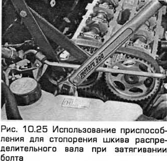
25. If any of the camshafts is significantly displaced from the required position, then using the device described in paragraph 18. while holding the shaft pulley from turning, release the pulley mounting bolt. After that, the camshaft can be turned (carefully working with a wrench) so that the camshaft is aligned with the alignment tool. Be careful not to disturb the engagement of the pulley with the toothed belt. Without violating the new position of the pulley on the camshaft, tighten the pulley bolt to the required torque (see fig. 10.25). Remove the camshaft alignment tool, turn the crankshaft two turns clockwise and reinstall the tool to make sure it is in the correct position.
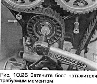
26. After the belt has a normal position and tension, and when the crankshaft pulley marks are aligned, the camshaft alignment tool will fit exactly into their slots, tighten the tensioner bolt to the required torque (see fig. 10.26). Holding each pulley by its spokes with a scissor tool, make sure the pulley bolts are tightened to the correct torque. Remove the camshaft alignment tool, turn the crankshaft two turns clockwise and reinstall the alignment tool for a final check.
27. On production models from 05.1998, please note that the tensioner constantly and automatically adjusts the tension due to the force of the internal spring. Therefore, it is not possible to check the tension by pressing on the belt or turning it.
28. The remaining operations are performed in the reverse order of withdrawal, taking into account the following:
- A) Tighten all fasteners to the required torque.
- b) When installing the right engine/transmission mount, replace the self-locking nuts and do not allow the mount to wobble when tightening the two (located in the middle) of six bracket nuts.
Visitor comments