Warning: Gasoline is highly flammable. Take special care when working on the fuel system. Work in a well ventilated area - open all windows and doors to create an exhaust hood. Do not smoke or allow naked flames or incandescent lamps without protective covers near the work area. Please note that the fuel used in household appliances (heaters, boilers, dehumidifiers), also poses a risk. Keep this in mind when working near such equipment. Near the working area, it is always necessary to have a fire extinguisher suitable for extinguishing burning oil products, and before starting work, you must read the instructions for its use. Protect your eyes when working on the fuel system (goggles, visor, etc.), If fuel comes into contact with skin, wash immediately with soap and water. Please note that fuel vapors are just as dangerous as liquid fuels.
Withdrawal
1. Park the vehicle on a firm, level surface. Apply the parking brake and loosen the right front wheel nuts.
2. Relieve pressure in the fuel system (chapter 4).
3. Disconnect the negative battery cable (chapter 5, paragraph 1).
4. Disconnecting the two electrical connectors and disconnecting the vacuum hose (if available), remove the air cleaner cover assembly with air mass meter, resonator and prechamber (chapter 4A).
5. Disconnect the accelerator cable from the throttle linkage (chapter 4A). Disconnect also the speed control cable (in the presence of) (chapter 12).
6. Disconnect the crankcase ventilation hose from the fitting on the head cover.
7. Turn out bolts in the top part of a heat-insulating casing of a final collector. Detach the coolant hose so that the cover can be removed. Loosen the EGR pipe nut (RVG) to the collector. Remove the two screws securing the pipe to the ignition coil bracket. And then unscrew the nut that secures the pipe to the valve of the RVG system (chapter 6).
8. Remove the two screws securing the wiring trough to the top of the manifold. This is necessary so that it can be moved as needed to access the manifold bolts. Disconnect the electrical connectors of the camshaft position sensor and the coolant temperature sensor. Then detach the wiring from the ignition coil bracket and fix it to the manifold.
9. Remove the three screws securing the wire tray to the back of the manifold. Release the wiring clamps, disconnect the large electrical connector (next to the fuel pressure regulator) to disconnect the wiring of the manifold components from the engine wiring harness.
10. Marking the vacuum hoses as they are removed, disconnect them in the following sequence:
- A) Hose from rear of throttle body (the second hose going to the fuel pressure regulator does not need to be removed).
- b) Hose from the fitting on the left end of the manifold.
- V) brake booster hose (chapter 9).
- G) Hose from the RVG system valve.
11. Equalize the pressure in the fuel tank by removing the filler cap. Then peel off the injection and drain fuel lines attached to the chassis (chapter 4). Plug or cover all connection openings.
12. Turn out bolts of fastening of the pipeline of forcing of a hydraulic system of a steering. Remove the ground wire bolt from the engine lifting eye/rear head base plate. Then, unscrew the bolt that secures the lifting eye/base plate to the alternator support bracket.
13. Turn away six nuts of fastening of an arm of the right support of the engine/transmission. Then remove the bracket.
14. Remove the generator (chapter 5).
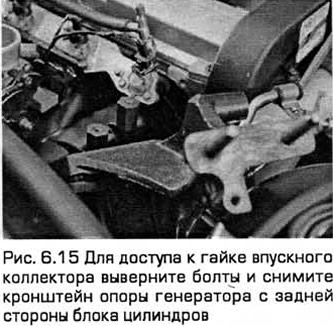
15. Turn out bolts of fastening of an arm of a support of the generator to a back part of the block of cylinders. Pull out this bracket along with engine lifting lug/rear head support plate (see fig. 6.15).
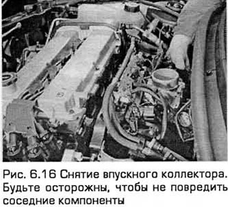
16. Turn out bolts and nuts of fastening of a collector to a head of the block and pull out it (see fig. 6.16). Be careful not to damage adjacent components such as the EGR valve and pipe.
Installation
17. Installation - in the reverse order of removal, taking into account the following:
- A) When removing used gasket residue and sealant from the manifold and head with a scraper and solvent, be careful not to scratch or damage the manifold or head. The head of the block is made of aluminum alloy, and the manifold is molded from plastic, so suitable solvents must be used. If the gasket is leaking, have the joint surface checked by a bodyshop for warping. The head gasket surface can be treated if necessary, and the manifold, if warped or cracked, needs to be replaced. Pay particular attention to the presence of warpage, cracking of the attachment points to the manifold of components such as the idle control valve and the EGR system piping.
- b) Provided that the respective mating surfaces are clean and flat, the installation of a new gasket provides a gas-tight joint. Do not use any silicon-based sealants to seal fuel system or intake manifold components.
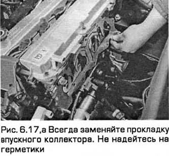
- V) Install a new gasket. Then install the manifold on the block head. Install nuts and bolts (see fig. 6.17, a).
- G) Torque tighten nuts/bolts (in three or four stages - see Specifications). Tighten them sequentially from the center to the edges so that the collector does not warp.
- d) Install the remaining components in the reverse order of removal. Tighten all fasteners to the required torque.
- e) When rebuilding the right engine/transmission mount, replace the self-locking nuts and prevent the mount from rocking while tightening the middle two of the six bracket mounting nuts.
- and) Before starting the engine, check that the accelerator cable is properly adjusted and that the throttle linkage operates smoothly.
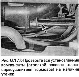
- h) When the engine is fully warmed up, inspect it for fuel leaks, as well as for intake tract leaks and/or vacuum leaks (see fig. 6.17, 6). Check the car on the road and check if all installed components work reliably.
Visitor comments