Withdrawal
Note: On models prior to 05.1998, you will need an assistant and special equipment to lift the vehicle to perform this procedure when the power unit is installed in the vehicle (to the height required to pull out the pallet from below), as well as for lifting the power unit by 50-75 mm relative to its supports and supporting it with the car already raised. Features of the procedure will depend on the equipment you use. A typical procedure is described below. On models manufactured from 05.1998, it is not necessary to jack up the engine.
1. Apply the parking brake. Raise the front end and place it on stands.
2. Drain the engine oil. Then flush and install the drain plug. Tighten it to the required torque. Recommended (although this is not required) When changing the oil, also change the oil filter (Chapter 1). Therefore, we advise you to remove and discard the old filter.
Release models prior to 10.1996
3. Disconnect the negative battery cable (see ch. 5 paragraph 1).
4. Empty the cooling system (Chapter 1).
5. Disconnect the bottom hose of a radiator from a branch pipe of a radiator and a heater pipe. Turn out bolts of fastening and disconnect the pipeline of a cooling liquid from the pallet. Disconnect the coolant hoses from the oil cooler (if available), if they interfere with the removal of the pallet.
6. Turn out two bolts of fastening of the pipeline of a hydraulic system of a steering to the right side of a stretcher.
7. Disconnect the oxygen sensor electrical connectors and (in the presence of) oil level sensor.
8. On models with automatic transmission, trace the transmission fluid cooling route from the transmission to the radiator and release the pipelines of the route from their fasteners so that they can be mixed as needed.
9. Remove the accessory drive belt cover (Chapter 1).
10. Having turned off the corresponding nuts, disconnect a reception pipe of an exhaust system from a collector. Then unfasten all rubber braces and pull the exhaust system assembly out from under the vehicle, or remove just the downpipe/catalytic converter (chapter 4A).
11. Turn out bolts of fastening of the pallet to transmission, and also release the lower adapter plate of the engine/transmission from fastening.
12. Disconnect the wiring connectors, disconnect the vacuum hose (in the presence of) and disconnect the crankcase ventilation hose from the head cover. Then remove the air cleaner assembly along with the air mass meter, resonator and air duct chamber (chapter 4A).
13. After that, you need to hang the power unit by the cargo eyes located on the head of the unit. Where required, screw in additional load eyes (see fig. 16.13). Remove the entire front engine/transmission mount. Turn out the central bolt of a back support and turn out bolts of the left support from a body. Remove the six nuts securing the right support bracket and remove the bracket.
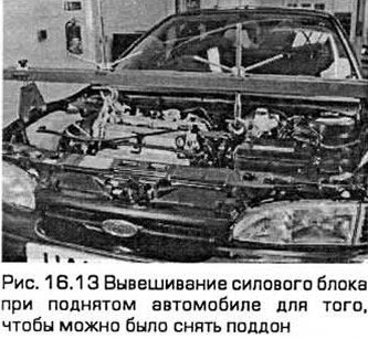
14. Be careful not to damage wiring, coolant hoses, radiator lines or transmission linkage and transmission support rods (depending on version), as well as the electric fan of the radiator of the cooling system. Raise the power block by 75 mm and fix it securely.
15. Consistently turn out fixing bolts of the pallet. Separate the joint by tapping on the pallet with the palm of your hand. Then, lower the pan and pull it out together with the bottom adapter plate of the power unit. Pay attention to the presence of any shims between the pan and transmission.
16. Remove and discard pan gasket. Once removed, it must always be replaced.
Release models from 10.1998 to 05.1998
17. Remove the engine oil level dipstick.
18. On models with a 2.0 liter engine, release the coolant hose from the fasteners on the exhaust manifold heat shield.
19. Turn out the top and bottom bolts and remove the heat-insulating screen from a final collector.
20. Locate the connector for the wiring coming from the oxygen sensor located on the exhaust manifold and disconnect it.
21. Remove the nuts and disconnect the catalytic converter from the exhaust manifold. Rest it on a pedestal.
22. Hang the engine with a hoist.
23. Loosen the right suspension strut upper mount nut 5 turns while holding the damper rod with a hex wrench.
24. Remove the protective shield from under the engine.
25. Remove the flange bolts and disconnect the catalytic converter from the intermediate section of the exhaust system. Release the transducer from rubber extensions and take it out from under the car.
26. Remove the right drive shaft (chapter 8).
27. Remove the center bolts from the front and rear engine roll stops.
28. Turn out a bolt and disconnect an arm of a pipe of system of cooling from the pallet.
29. Mark the position of the right engine mount. Then turn out bolts and remove an arm.
30. Raise the power block 75 mm and fix it securely.
31. Consistently turn out fixing bolts of the pallet. Separate the joint by tapping on the pallet with the palm of your hand. Then, lower the pan and pull it out together with the bottom adapter plate of the power unit. Pay attention to the presence of any shims between the pan and transmission.
32. Remove and discard pan gasket. Once removed, it must always be replaced.
Release models from 05.1998
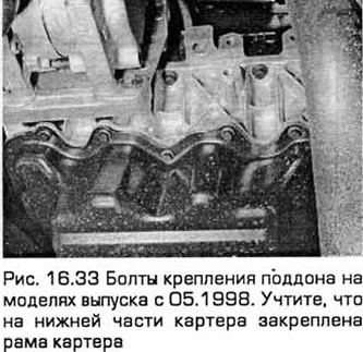
33. When the front of the car is raised, sequentially unscrew the fixing bolts of the pallet (see fig. 16.33). Separate the joint by tapping on the pallet with the palm of your hand. Then turn the drip tray 90°, lower it and pull it out. The pallet has no gasket.
Installation
34. When installing, carefully clean the mating surfaces of the cylinder block / crankcase and sump, and also remove grease from them. Then, with a clean rag, wipe the pan and the inside of the engine.
Release models prior to 10.1996
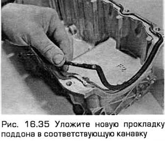
35. Lay a new gasket in the groove of the pallet (see fig. 16.35).
36. If you install a sump when the engine and transmission are connected and installed in the vehicle, follow these instructions:
- A) Make sure that the mating surfaces of the sump, cylinder block/crankcase and transmission are smooth and perfectly clean. If the pallet was removed along with the adjusting washers, then they must be installed in their places.
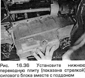
- b) thin layer of sealant (Ford recommends HYLOSIL102) lubricate the joints of the cylinder block / crankcase with oil pump and the cylinder block / crankcase with the housing of the left crankshaft seal. The pan bolts must be fully tightened within 10-20 minutes after the sealant has been applied. Lift the tray and bottom adapter plate of the power unit, install the bolts and lightly tighten them (see fig. 16.36).
- V) Convinced that. that the lower adapter plate of the power unit is installed correctly, press the sump to the transmission and tighten the bolts securing the sump to the transmission to the required torque.
- G) Without violating the position of the pallet, tighten the bolts of the pallet to the required torque in a cross sequence, starting from the middle to the edges.
- d) Follow the instructions in paragraph 38.
37. If you install a sump when the engine and transmission are disconnected (inside or outside the car), follow the instructions below:
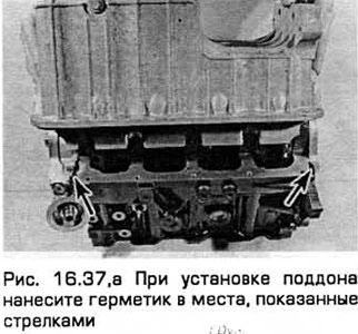
- A) thin layer of sealant (Ford recommends HYLOSIL 102) lubricate the joints of the cylinder block / crankcase with oil pump and the cylinder block / crankcase with the housing of the left crankshaft seal. The pan bolts must be fully tightened within 10-20 minutes after the sealant has been applied. Raise the pallet, install the bolts and tighten them slightly (see fig. 16.37.а).
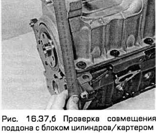
- b) With a ruler (see fig. 16.37.6), installed on the machined surfaces of the cylinder block and pallet, set the left end of the pallet (together with the washers if you removed them together with the pallet) flush with the spruce end of the cylinder block/crankcase. The pallet is not mixed, tighten its bolts to the required torque in a cross sequence, from the center to the edges.
- V) Check again that the exposed ends have not moved. If necessary, unscrew the pan bolts again, clean the mating surfaces and repeat the entire procedure to ensure proper installation.
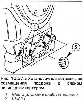
- G) If it is not possible to accurately set the pallet, then to achieve the required position, place shims with a thickness of 0.25 mm (yellow color) or 0.50 mm (black color) (see fig. 16.37, in).
38. Perform the remaining installation operations in the reverse order of removal, taking into account the following:
- A) Tighten all fasteners to the required torque.
- b) Self-locking nuts removed during removal must always be replaced.
- V) Lower the power block into place and restore the rear, left and right supports. The weight of the power unit must not be transferred to the supports, it must be taken up by the lifting device until all supports are properly aligned.
- G) Install the Ford special tool in place of the front support, tighten the fasteners of the power block supports to the required torque in the sequence indicated (chapter 2B).
- d) Recharge the cooling system (Chapter 1).
- e) Fill the engine with oil and do not forget to install a new oil filter (Chapter 1).
- and) Immediately after starting and warming up the engine to normal operating temperature, check for oil or coolant leaks.
Release models from 10.1996 to 05.1998
39. Lubricate with a thin layer of sealant the joints on the cylinder block under the oil pump and the rear cuff housing, as well as the reciprocal places on these components.
40. Lay a new gasket on the pallet and attach the pallet to the cylinder block. Insert the sump-to-cylinder block bolts and torque tighten to stage 1.
41. Install adapter plate. Then press the pan against the clutch housing. Insert bolts of fastening of the pallet to transmission and tighten them the demanded moment.
42. Tighten bolts of fastening of the pallet to the block of cylinders the demanded moment on stage 2.
43. Lower the engine and install its right support in the position marked during removal. Tighten bolts and nuts to the required torque.
44. Install the coolant pipe bracket and tighten the bolt.
45. Install and tighten the engine roll stop bolts. If necessary, check their position and adjust them (paragraph 23).
46. Install the right drive shaft (chapter 8).
47. Install the catalytic converter (chapter 4A).
48. Install the protective shield.
49. Tighten the nut of the upper support of the right suspension strut to the required torque (chapter 10).
50. Remove the lift.
51. Connect the oxygen sensor wiring connector.
52. Install the exhaust manifold heat shield and tighten its bolts.
53. On models with 2.0 liter engines, lay the coolant hose on the support points under it on the heat shield.
54. Install the oil level dipstick. Lower the car to the ground and fill the engine with oil (Chapter 1).
Release models from 05.1998
55. Apply a 3 mm thick bead of sealant to the sump flange at a distance of about 5 mm from its outer edge. The sealant must also surround the bolt holes. Install the pan within 10 minutes of applying the sealant.
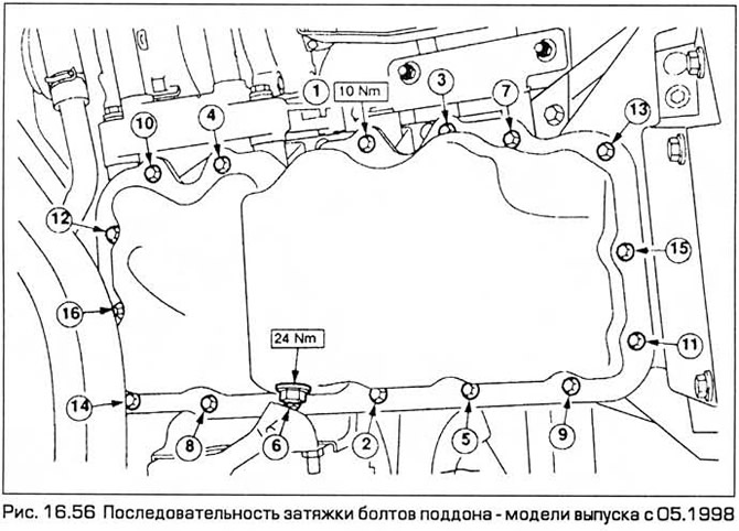
56. Insert the bolts and tighten them sequentially to the required torque (see fig. 16.56).
57. Lower the car to the ground and fill the engine with oil (Chapter 1).
Visitor comments