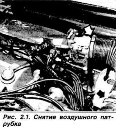
Disconnect the wires from the battery Disconnect the windshield washer hoses from the hood and remove the hood from its hinges. Remove the crankcase suction hose from the cavity of the cylinder head cover to the intake manifold. Remove the air filter and disconnect the vacuum hose from the intake manifold. On engines with injection, remove the air pipe connecting the dispenser-distributor to the housing (pic. 2.1) throttle valve.
Drain the coolant into the prepared container and disconnect the hose from the lower radiator pipe. Remove the upper radiator hose. On engines with injection, also remove the hose connecting the thermostat, water pump and oil cooler tee. Release clip and disconnect throttle cable with bracket. On injection engines, disconnect the wires from the starter injector. control pressure regulator, thermal time switch, additional air supply valve and jumper «masses» from the throttle body. Disconnect the fuel supply hose from the fuel pump, and the vacuum supply hose to the vacuum brake booster from the inlet pipeline. On engines with injection, in addition, remove the fuel supply hoses to the control pressure regulator, the starting injector and the dispenser, plug all openings in the fuel lines, disconnect the vacuum supply hose to the electromagnetic shut-off valve and the crankcase ventilation valve hose. Disconnect the wires from the alternator, oil pressure sensor, ignition coil, solenoid shutoff valve, reverse light switch, and oil level sensor (depending on configuration), and on engines with injection, in addition, disconnect the wires from the starting injector, control pressure regulator, thermal time relay. auxiliary air supply valve, throttle position sensor, as well as a jumper «masses» throttle valve. Unscrew the nut securing the flexible shaft of the speedometer drive and remove the cable from the clutch fork lever.
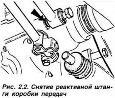
Remove heat shield (on the GLA engine - air heating casing) and disconnect the exhaust pipe from the exhaust manifold. Place the car on stands. The stands must be high enough to allow the engine to be removed by lowering it down. Loosen the fastening parts of the exhaust tract and remove it. Disconnect wires from starter and jumper «masses» engine. Release the shift linkage and return spring Disconnect the transmission torque rod (pic. 2.2) Loosen the cap nut of the shift rod retainer. Remove the spring and retainer and drain the oil from the gearbox housing. Remove the suspension arm from the right side of the vehicle.
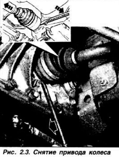
Install the tool as shown in fig. 2.3, press the wheel from the inside out and with light blows of the hammer knock the drive shaft out of the gearbox. Hang the drive shaft to the body. To prevent movement of the differential gears, install a plastic plug or an old drive inner joint. Remove the suspension arm on the left side, remove the left wheel drive shaft and hang it to the body.
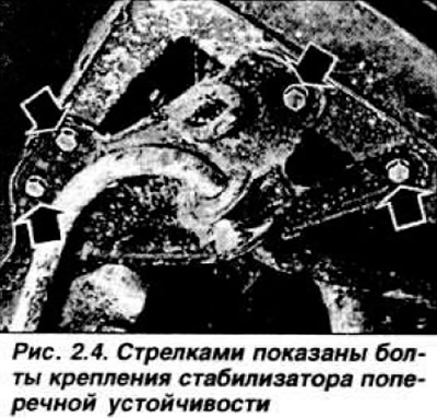
Loosen the front and rear gearbox mounting bolts. Moor the power unit. Loosen the nuts securing the longitudinal stretching of the suspension (only on vehicles with GLA engine). unscrew the mounting bolts and remove the anti-roll bar (pic. 2.4). Unscrew the nuts of the studs securing the engine mounts to the side members and the bolts of the mudguards of the front fenders. Carefully lower the power unit down.
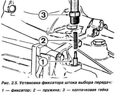
Before installing the power unit, apply sealant like Omni Fit 3 OM to the threads of the cap nut. install the shift rod retainer and spring and tighten the cap nut (pic. 2.5).
From below, bring the power unit into the engine compartment, lifting it so that it is possible to insert the studs of the engine mounts into the holes of the side members. Install and secure the front mudguards. Install and secure the anti-roll bar (and longitudinal stretching on a car with a GLA engine). Install two gearbox mounting bolts and brackets and lower the power unit. Remove the chocks and tighten the engine and gearbox mountings. Install the coolant hose bracket.
Install the left wheel drive with a new circlip. Insert the ball joint pin of the suspension arm into the hole of the steering knuckle, install a special bolt and tighten the joint nut to a torque of 7.5-9.0 kgf·m. Remove the plastic plug or old CV joint and install the right wheel drive with a new circlip. Install the suspension arm on the right side. Install the torque rod of the gearbox, put a washer between the rod and the gearbox housing. Make sure. that the highest (IV or V) gear is engaged, and connect the gearshift linkage to the gear selector rod. Using tool 16-032 for 5-speed gearbox or 3.5 mm drill bit shank, pull the shift rod down and secure it to the support cup yoke. Using a drift, turn the gear selector rod clockwise until it stops and push it into the crankcase.
Using a rubber ring inserted behind the cap nut of the retainer, secure the stem in this position and tighten the bolt of the stem fastening clamp. Remove the rubber band, remove the drill and attach the return spring to the drive rod. Connect jumper «masses» engine and wires to the starter. Install the exhaust tract on supports with rubber cushions. Install air heater cover (only on vehicles with GLA engine). Install a new gasket and attach the downpipe to the exhaust manifold. and for engines of the GMA and GPA models. in addition, install a heat shield. Connect the speedometer cable to the gearbox and the clutch cable to the fork lever. Connect the wires to the alternator, coolant temperature sensor, oil pressure sensor, ignition coil, reverse light switch and oil level sensor (if it is installed). Connect the vacuum brake booster hose to the intake manifold and the fuel supply hose from the fuel pump.
On engines with fuel injection, connect the crankcase ventilation hose to the valve, the vacuum supply hose to the auxiliary air supply valve, connect the fuel lines to the dispenser-distributor, to the starting injector, to the control pressure regulator. Connect wires to start injector, pilot pressure regulator, thermal time switch, auxiliary air valve, and throttle body Install throttle cable bracket to carburetor and connect cable. Connect the hoses and fill the cooling system.
Pour oil into the engine and gearbox. Install the hood and windshield washer hoses. Connect the wires to the battery. On engines with fuel injection, install a pipe connecting the metering distributor to the throttle body. Adjust the ignition and CO content in the exhaust gases. Install the air filter, the gas suction hose from the cavity of the cylinder head cover and the hose for the vacuum ignition timing regulator.
Visitor comments