Device Features
cylinder head (pic. 2.40) cast from aluminum alloy and has hemispherical combustion chambers. The volume of the combustion chambers for engines of the GMA and GPA models is: 43.11-45.93 cm3. JPA: 53.39-56.55 cm3. LPA and LUA: 53.01-56.21 cm3. LRA and L7: 53.36-55.38 cm3. Borings are made into the body of the cylinder head for the pushers and guides of the valve bushings and for the bushings of the camshaft bearings, valve seats are pressed into it. The diameter of the holes for the pushers is 22.235-22.265 mm. The cylinder head gasket is installed with a label «Thor» towards the head (edging of openings towards the block of cylinders). Gasket designation for GMA and GPA engines is 81 SM-6051-N2D; 81SM-6051-N3D; JPA, LPA, LUA, LRA, and L7 - 81 SM-6051-R2D; 81 SM-6051-R3D.
Valve seats
Valve seats have a seat angle of 45°, top face angle: nominal 18° (30°for LRA and L7 engines). repair 15°; bottom chamfer: nominal 77-70°, repair 75-70°. Saddle width 1.75-2.32 mm.
Guide bushings
The valve guides are made of special cast iron and are pressed into the cylinder head. The diameter of the holes in the guide bushings of the intake and exhaust valves: nominal size 8.063-8.094 mm, repair size with an increase of 0.2 and 0.4 mm.
Valves
The valves are made of special steel and mounted with an outward slope on both sides of the camshaft; are driven by a camshaft through hydraulic tappets and rocker arms, as a result of which there are no gaps in the valve drive mechanism (the L7 engine has mechanical pushers) (pic. 2.40).
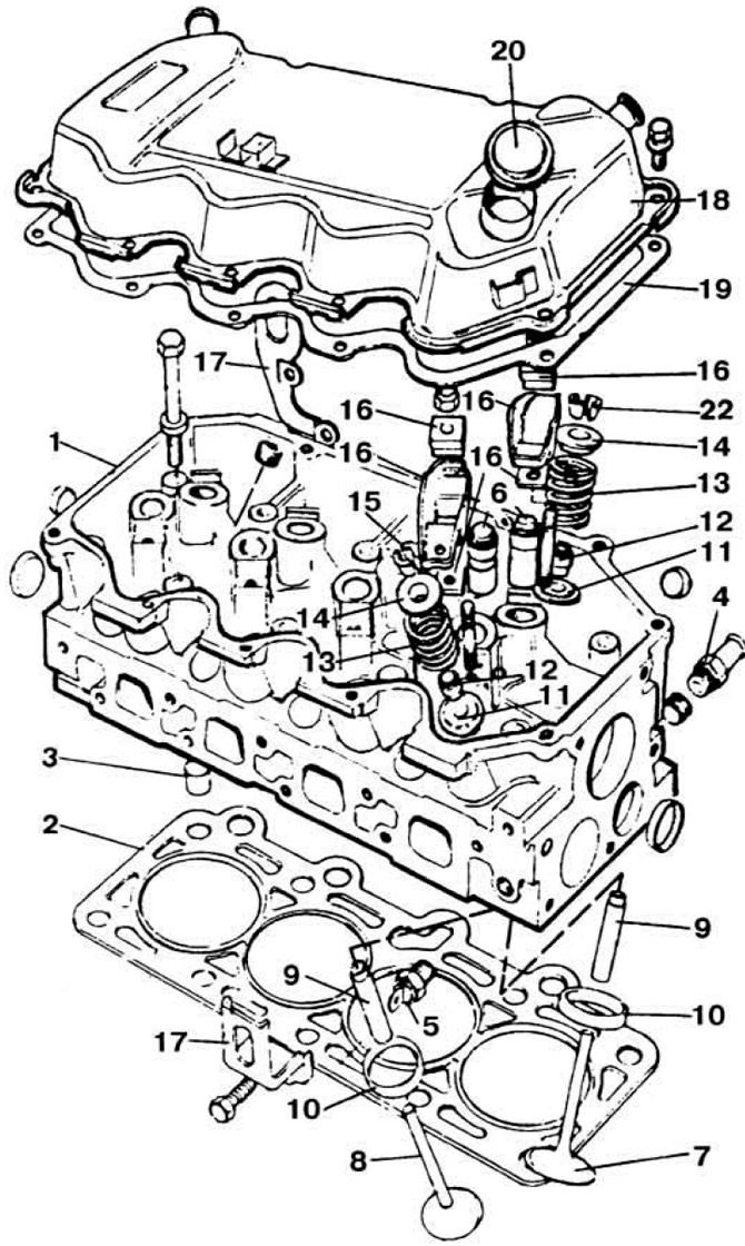 Pic. 2.40. Cylinder head for all models except GLA.
1 - cylinder head; 2 - cylinder head gasket; 3 - centering sleeve; 4 - water pipe; 5 - coolant temperature sensor; 6 — hydraulic pushers; 7 - inlet valve; 8 - exhaust valve; 9 - valve guides; 10 - valve seats; 11 - spring washers: 12 - oil seals; 13 - valve springs; 14 - valve plates; 15 - crackers; 16 - details of the rocker; 17 - lugs for lifting the engine; 18 - cylinder head cover; 19 - gasket; 20 - oil filler cap.
The valve springs are the same for intake and exhaust valves. The height of the spring in the free state is 47.2 mm. valve open 27.7 mm, valve closed 37.084 mm. The force of compression of the spring with the valve open is 85.33-93.21 kgf. with a closed valve 40.14-44.16 kgf. The rocker arms are stamped steel and are secured with one bolt each. hydraulic (except model L7) the pushers are hollow, made by drawing from a steel billet. The diameter of the pushers is 22.25 mm. the diameter of the holes for the pushers in the cylinder head is 22.235-22.265 mm.
Adjustment of gaps in the valve drive mechanism of the engine model L7
This operation is performed on a cold engine. The gap between the adjusting washer and the end of the valve is 0.15 mm for intake valves and 0.30 mm for exhaust valves and is adjusted with a special pin key. Since the adjusting screws 1 (fig 2.41) are made of very hard material, if they are difficult to rotate, the pin key can be broken.
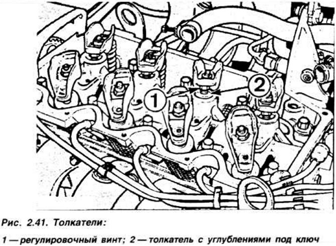
Therefore, it is necessary to unscrew the screw from the pusher, clean its threads, tighten it again, put the pusher and rocker in place and adjust the gap. When installing the rocker arms, replace the self-locking nuts with new ones. Catalog numbers for pin wrench 9059235, fork wrench 9059226.
Removal and installation of a head of cylinders of engines of the GMA, GPA, JPA, LPA And LUA models
Disconnect the wire from the output «minus» battery and remove the air filter. Disconnect the lower hose from the radiator and drain the coolant into the prepared container. Disconnect the hoses from the radiator, thermostat housing and from the automatic starter. Remove the clamp, disconnect the throttle cable and remove it together with the carburetor mounting bracket. Disconnect the fuel pump and brake booster hose from the intake manifold. Disconnect the electrical wires from the switch on the electric fan. ignition coils, coolant temperature sensor and solenoid shut-off valve. Remove the heat shield and disconnect the muffler pipe from the exhaust manifold. Loosen the alternator and remove the drive belt. Remove the camshaft timing belt cover by unscrewing the four bolts and loosen the two belt tensioner bolts.
Move the belt tensioner to the left, tighten the bolts of its fastening and remove the toothed belt. Disconnect the high voltage wires, remove the ignition distributor cap and unscrew the spark plugs. Remove the crankcase ventilation hose from the pipe on the cylinder block, unscrew the nine bolts and remove the cylinder head cover. Loosen the cylinder head bolts in the reverse order of their tightening (pic. 2.42). Remove cylinder head with intake manifold and exhaust manifold.
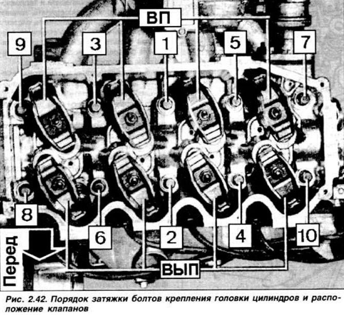
Before installing the cylinder head, make sure that the dowel sleeves are present and install the cylinder head gasket with the lettering facing up Turning the crankshaft. set the piston of the first cylinder to a position 2 cm below TDC to avoid damaging the valves. Install the cylinder head and tighten the new mounting bolts in four steps (pic. 2.42).
Tightening torque: 1st stroke 2.5 kgf·m, 2nd stroke 5.5 kgf·m; then turn 90°further and turn 90°again.
Install the toothed pulleys of the crankshaft and camshaft according to the marks to their original position and put on the toothed belt of the timing mechanism drive (see section «Camshaft»). Apply sealant (to specification Ford A 70 SX 19554-BA) in the form of a roller 2-3 cm long on the mating surface of the cylinder head from the side of the drive of the gas distribution mechanism and from the side of the carburetor. Install a new cover gasket on the cylinder head and tighten the cover fastening bolts to a torque of 0.6-0.8 kgf·m.
Install the front toothed belt cover, accessory drive belt and tension it. Screw in the spark plugs, install the ignition distributor cap and high voltage wires. Install the throttle cable and bracket. Connect the wire to the coolant temperature sensor. Connect the wires of the ignition coil, the switch on the electric fan and the electromagnetic shut-off valve. Install the vacuum brake booster and fuel supply hoses to the carburetor. Install the exhaust manifold with a new gasket and heat shield. Connect the cooling system hoses and fill the system with coolant.
Install the air filter and connect the battery. Check ignition setting and idle speed. The intake piping and exhaust manifold of the LRA and L7 engines are different, so the removal and installation of the cylinder head of these engines differs from those described above. Disconnect the wire from the negative battery terminal. Remove the crankcase breather hose. Remove the air filter and vacuum hose from the intake manifold. Remove the air pipe connecting the dispenser-distributor to the throttle body.
Disconnect the wires from the starting injector, control pressure regulator, thermal time switch, auxiliary air valve and jumper «masses» solenoid shut-off valve on the throttle body. Remove the fuel supply hoses to the control pressure regulator, the starting injector and the dispenser. Disconnect the vacuum hose from the shut-off valve. After removing the hose from the control pressure regulator, disconnect the crankcase ventilation hose from the cylinder head cover, disconnect the hose from the thermostat housing and remove the injector mounting brackets. After disconnecting the vacuum brake booster hose from the intake manifold, disconnect the wires from the coolant temperature sensor and from the fuel dispenser. You can remove the cylinder head after its temperature drops to ambient temperature. The cylinder head is installed in the reverse order of its removal, the injector mounting brackets and the receiver are installed after the intake pipe and exhaust manifold are installed.
Dismantling and assembly of a head of cylinders
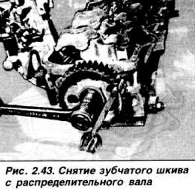
Place the cylinder head on two wooden stands to prevent damage to the valves. Remove the exhaust manifold and intake manifold with carburetor assembly. Remove the ignition distributor and thermostat housing. Using a screwdriver, block the camshaft pulley, unscrew its fastening bolt (pic. 2.43).
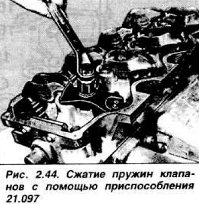
Remove and lay in order the rocker arms with guides and thrust bushings. Compress valve springs with tool 21.097 (pic. 2.44), remove crackers, release the tool and remove the upper plates, springs and support washers of the valve springs.
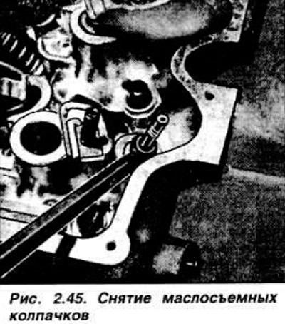
Remove using a screwdriver (pic. 2.45). valve stem seals and remove valves.
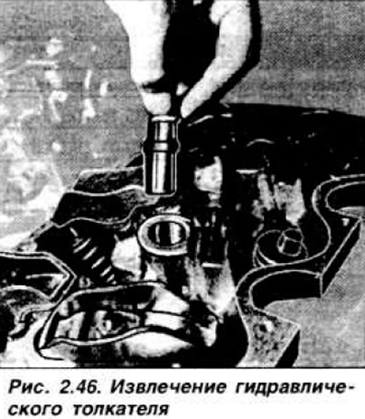
Remove and install pushers in order. Loosen the camshaft thrust flange bolts and carefully remove the camshaft towards the ignition distributor. Unscrew the coolant temperature sensor and the heater hose fitting. If necessary, unscrew the studs securing the intake and exhaust manifolds.
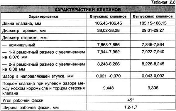
Before assembling the cylinder head, it is necessary to check the clearance between the valves and the guide bushings and the condition of the working chamfers of the valve seats. To do this, insert the valves into the guide bushings and use a dial indicator to determine the gap. If the result obtained exceeds 0.020-0.063 mm for intake valves and 0.046-0.089 mm for exhaust valves, it is necessary to expand the holes in the bushings to the next repair size (see table 2.6) using reamers 21.071-21.074. The tool must be entered from the side of the combustion chambers. Then it is necessary to countersink the valve seats with a special cutter, observing the angles indicated above. After countersinking, grind the working chamfers and grind the valves. Thoroughly clean the head, blow out the guide bushings and valve seats with compressed air. Scratches and burrs on the working facets of valves and seats are not allowed.
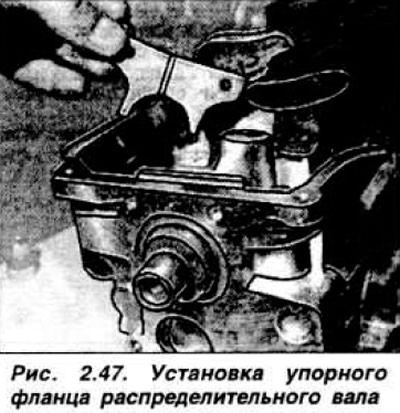
Screw in the intake and exhaust manifold studs, if they have been removed. Install the coolant temperature sensor and the heater hose fitting. Lubricate the camshaft journals and bearing bushes in the cylinder head, as well as the thrust flange with engine oil. Install the camshaft into the cylinder head, starting it from the rear, being careful not to damage the bushings. Install thrust flange (pic. 2.47) and tighten the bolts of its fastening with a torque of 1.0-1.5 kgf·m.
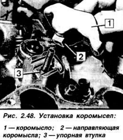
Lubricate the tappets with engine oil and install them in their respective sockets. Lubricate the valve stems with hypoid oil and install the valves in the guide bushings, install the spring support washers. Seal the grooves under the crackers on the valve stems with adhesive tape, lubricate the new valve stem seals with oil and use the Ford 21.007 mandrel to install the caps on the valve guides. Remove adhesive tape, install valve springs and upper spring plates. Compress the valve springs with tool 21.097 and fit the poppet retainers. Install thrust bushings and rocker arms with their guides (pic. 2.48), paying attention to the correct fit.
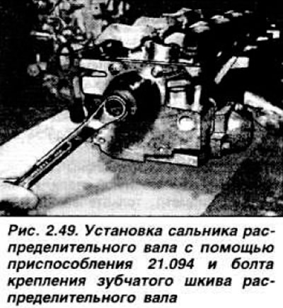
Screw in the new rocker arm nuts and tighten them to a torque of 2.1-2.5 kgf·m. Install a new camshaft oil seal using special tool 21.094 and the camshaft sprocket bolt (pic. 2.49).
Install the camshaft pulley and tighten the fastening bolt to a torque of 5.4-5.9 kgf·m. Install the thermostat housing. Replace the O-ring under the ignition distributor and install the ignition distributor. Lubricate the fuel pump tappet with engine oil and install the fuel pump. Install the intake manifold and exhaust manifold with new gaskets.
Visitor comments