Device Features
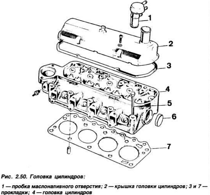
Cylinder head cast (pic. 2.50) made of cast iron and has wedge-shaped combustion chambers. The in-line valves are installed with an inclination of 15°from the vertical and are actuated through pushers, rods and rocker arms from a camshaft located in the cylinder block. Combustion chamber volume 26.888-29.888 cm3. Holes for pusher rods, guide bushings and valve seats are made in the body of the head. The gasket is installed with a label «Thor» towards the head.
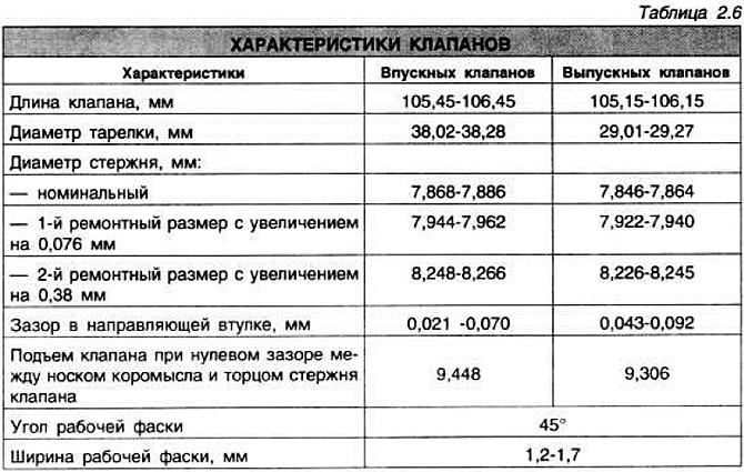
The valve seats have a chamfer angle of 44°30'-45°. The width of the working chamfer of the saddle is 1.2-1.75 mm for inlet valves. 1.5-1.7 mm for graduation.
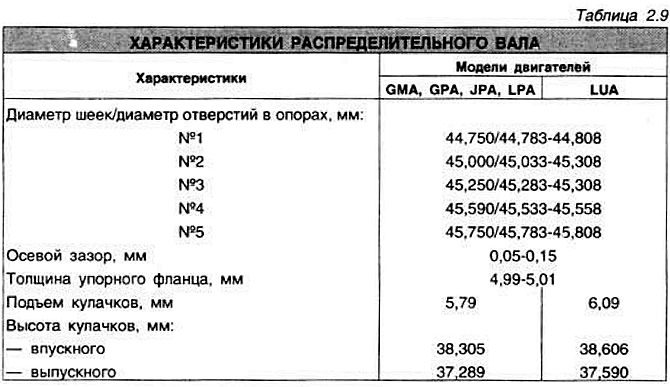
The valve guides are made of special cast iron and are pressed into the cylinder head. The diameter of the holes in the bushings is 7.907-7.938 mm. outer diameter of the nominal size bushing 13.081-13.094 mm. Valves are made of special steel.
The valve springs are the same for the intake and exhaust valves, with six coils each. Spring inner diameter, mm: 20.25-20.75 mm, wire diameter 3.77-3.83 mm. The height of the spring in the free state is 42 mm.
The rocker arms are made of steel, the pushrods are made of hardened steel. The nominal diameter of the pushers is 13.081-13.094 mm. Mating clearance «pusher-hole» 0.016-0.062 mm.
Valve clearance adjustment
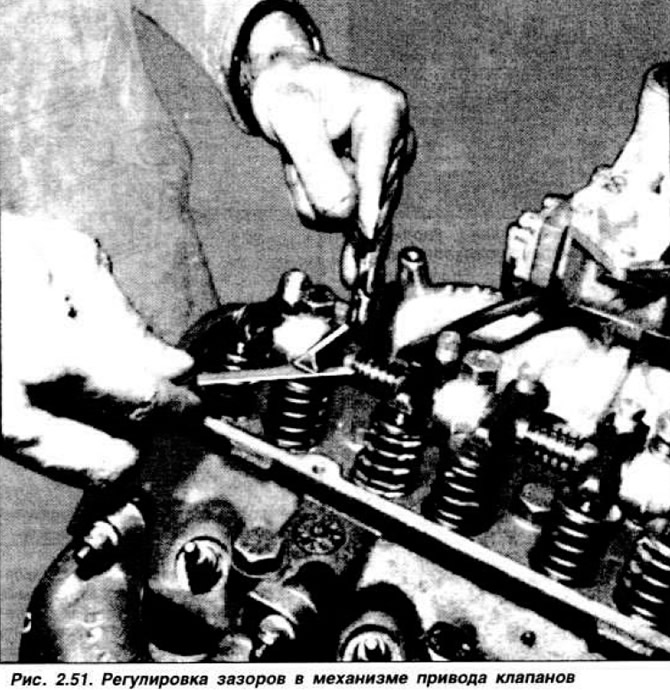
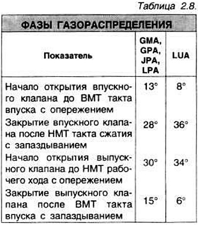
This operation is performed on a cold engine by the method «wiggle». Turn the crankshaft until the mark on its pulley aligns with the TDC mark on the timing cover. Remove the air filter and cylinder head cover. By rocking the crankshaft pulley in both directions. determine by the movement of the rocker arms. which cylinder valves (1st or 4th) pressed with rockers. If these are rocker arms of the 1st cylinder, then adjust the gaps of the 4th cylinder and vice versa. Then turn the crankshaft exactly 180°and adjust the gaps of the 2nd (or 3rd) cylinder. The order of operation of the cylinders is shown in Table 1.3, and the procedure for adjusting clearances in the valve drive mechanism is given in Table 2.7.

NOTE: Rectangular threaded adjusting screws have a significant amount of interference in the rocker arm. To avoid breakage of the screw, it is necessary to use a ring wrench that ensures uniform distribution of force over the screw head, and a drill of the appropriate diameter installed in the screw head (pic. 2.51). If the screw head is broken, replace the rocker arm assembly.
Removal and installation of a head of cylinders
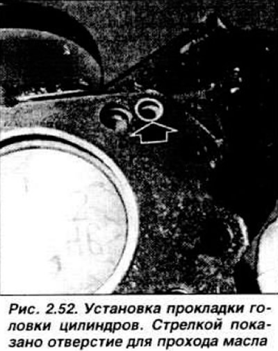
After removing the power unit from the car, remove the valve cover, rocker shaft. then remove the rods, lay in order; unscrew the mounting bolts and remove the cylinder head and gasket. When assembling the cylinder head, the gasket must be dry, clean and installed with a label to the head. Pay attention to the alignment of the oil passage holes in the gasket with the channels in the head (pic. 2.52).
Install the cylinder head, screw in the fastening bolts by hand. Tighten the cylinder head bolts in the order shown in Figure 2.14 in four steps: 1st step 1.0-1.5 kgf·m; 2nd reception 4.0-5.0 kgf·m; 3rd reception 8.0-9.0 kgf·m; 4th reception - 20 minutes after the 3rd reception, tighten the bolts to a torque of 10.0-11.0 kgf·m. Install the push rods by first dipping their ends in engine oil. Install the rocker arm axle and tighten the fastening bolts to a torque of 3.4-4.0 kgf·m. Adjust the clearances in the valve drive mechanism. Screw in and tighten the spark plugs to a torque of 1.5-2.0 kgf·m.
Dismantling and assembly of a head of cylinders
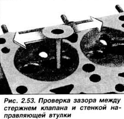
Using a special tool, compress the valve springs, remove the valve cotters. Then remove the spring plate, spring, lower support washer. From-draw and arrange the valves in order. Check the technical condition of the guide bushings (pic. 2.53), saddles and working chamfers of valves (see table 2.6).
In case of significant wear, repair parts. To ream the hole in the guide sleeve for the oversized valve, use reamer 21.042 (pic. 2.54).
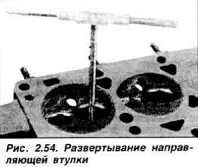
To do this, install the cylinder head with the seats up and gradually insert the tool into the guide hole, liberally lubricating the reamer with special oil or kerosene. If the guide bushings are excessively worn, which cannot be repaired with reamer 21.042, replace the cylinder head. After checking the guide bushings and their possible repair, check and, if necessary, restore the working chamfer of the valve seats. When chamfering a seat, use a specialized tool that centers the cutter or grinding stone on the seat. Do not allow cutting or scratches to appear on the working chamfer. Thoroughly clean and blow out the cylinder head with compressed air. After repairing the valve seats, grind the chamfers of the valves or replace the valves. In both cases, the valves should be lapped against the seats with a fine-grained grinding paste. After lapping, the valves must not be interchanged. In the case of installing a new cylinder head and working valves, their lapping is mandatory. After lapping the valves, thoroughly rinse and blow out the cylinder head with compressed air.
Disassembly and assembly of the axis of the rocker arms
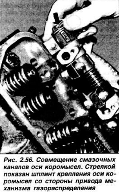
Remove the cotter pin, spring and support washer from the end of the rocker shaft. Remove the pushers, supports and spacer springs. In case of difficult descent of the supports, you can use a mallet with a plastic striker. Arrange the details in order. rinse in trichlorethylene and check their technical condition: wear of the axis of the rocker arms, fit of the toes of the rocker arms to the ends of the valve stems, the condition of the support washers and spacer springs. If necessary, replace defective parts: grind the toes of the rocker arms if they have nicks. Assemble the rocker shaft in the reverse order of disassembly, lubricating all parts with engine oil. Pay attention to the alignment of the lubrication channels: they must be directed downwards and forwards (pic. 2.56).
NOTE: If installing a new rocker shaft, make sure there is a plug on the timing drive side.
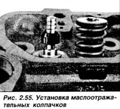
Before assembling the cylinder head, make sure all parts are clean. Lubricate the ends of the valve stems with engine oil and install them in the corresponding holes in the head. Lock the valves in the closed position with a suitable plate and install new slinger caps on the valve stems (fig.2.55) in the following order: wipe the valve stems with a lint-free cloth, wind adhesive tape into the grooves under the crackers, lubricate the valve stems and oil caps with oil, install the caps to the stop and remove the adhesive tape.
In case of improper installation of oil seals, oil consumption increases. Install the lower spring support washers, springs, upper spring plates, compress the springs with a special tool and install the crackers, paying attention to their correct position. Oil seals can be replaced without removing the cylinder head from the engine. To do this, the valve locking tool 21.056 and valve spring compression tool 21.057 are required.
Disconnect the negative cable from the battery. Remove air filter with bracket. Disconnect wires from spark plugs, remove cylinder head cover. Unscrew the spark plugs and remove the rocker shaft. Screw the valve locking tool into the hole for the spark plug, turn its central pin, bring it to the valve head and lock it in this position. Install the valve spring compressor 21.057 with emphasis on the rocker shaft mounting bolt, as shown in fig. 2.57.
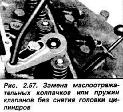
Compress the valve spring and remove the crackers (preferably with a magnet to prevent them from falling into the motor). Release the spring and remove the upper spring plate, spring and oil seal. Wrap adhesive tape into the annular grooves of the valve, lubricate the valve stem and a new oil seal and install it on the valve. Remove adhesive tape. Install washer, spring, valve disc. compress the spring with a tool and install the crackers. Repeat the operation for the remaining valves. After replacing the valve stem seals, install the rocker shaft and adjust the clearance in the valve drive mechanism. Install the remaining removed parts.
Camshaft and its drive (except for GLA model engine)
The engines use a cast iron camshaft. mounted on five bearings in the cylinder head and driven by a toothed belt from the engine crankshaft. From axial movement, the camshaft is held by a thrust flange attached to the cylinder head with two bolts.
The Motorcraft 81 SM 6268 GE camshaft drive toothed belt is tensioned by a roller tensioner. The tension moment of the toothed belt is 3.0-4.2 kgf·m for engines of the GMA, GPA, JPA models. LPA and LUA 2.0-3.2 kgf·m. Since 1982, the tension of the toothed belt has been changed and amounts to 6.0-6.5 kgf·m for engines of the GMA, GPA, JPA models. LPA, LUA, LRA and L7 4.5-5.0 kgf·m.
Removal and installation of a camshaft
Disconnect the negative cable from the battery, disconnect the crankcase ventilation hose and hoses from the intake manifold and cylinder head cover. Remove the air filter and disconnect the vacuum hose. Remove the washer reservoir. Disconnect the high voltage wires and remove the distribution sensor. Remove fuel pump with gasket and tappet. Remove the clip and disconnect the throttle cable from the bracket on the carburetor. Remove the crankcase ventilation hose from the nozzle on the cylinder block, then the cylinder head cover. Remove the rocker arms and lay them in order. Remove the pushers and lay them in order. Remove the alternator belt adjuster and remove the belt. Remove the toothed belt cover and, turning the crankshaft, align the marks on the camshaft pulley and cylinder head.
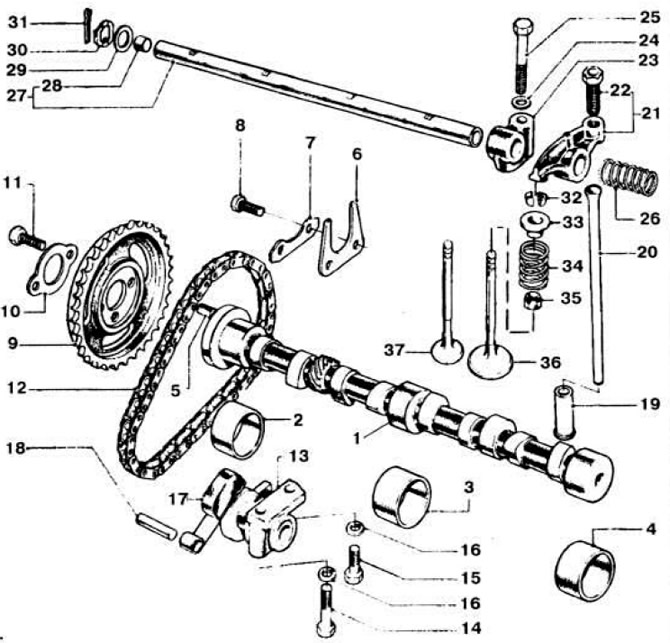
Loosen the bolts securing the roller tensioner, move it to the left and tighten the bolts. Remove toothed belt. Lock toothed pulley 2 (pic. 2.58) camshaft 11 with a screwdriver, unscrew the bolt of its fastening and remove the toothed pulley. Remove thrust flange 13 and carefully remove camshaft.
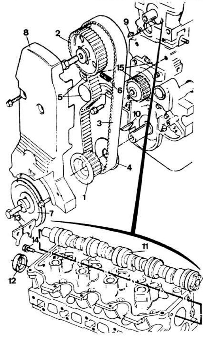 Pic. 2.58. Camshaft and its drive.
1 - toothed pulley of the crankshaft; 2 — a gear pulley of a camshaft; 3 - toothed belt; 4 - guide flange; 5 - belt tension roller; 6 - tensioner spring; 7 - crankshaft pulley; 8 — a cover of a gear belt; 9 and 10 - dowels; 11 - camshaft; 12 - stuffing box; 13 - thrust flange; 14 — a bolt of fastening of a persistent flange; 15 - toothed pulley of the water pump drive.
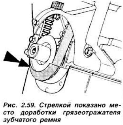
NOTE: As of May 1983, engines have been fitted with a new timing belt mudguard and two piece cover for easy access to the timing belt. The new cover can be installed instead of the old one. To do this, it is necessary to cut the dirt deflector with a hacksaw, as shown in fig. 2.59 without removing the cover and crankshaft pulley. Do not install a one-piece cover on an engine with a modified mud deflector or with a two-piece cover.
Before installing the camshaft, the oil seal must be removed. Lubricate the necks and thrust flange with engine oil. Carefully install the camshaft in the cylinder head and install the thrust flange. Install a new oil seal using drift 21.094. having previously lubricated its working edge. Install the toothed belt guard, put it on the pulleys and tighten the accessory drive belt. Lubricate and install the tappets in the appropriate sockets Install the rocker arms with new fastening nuts and tighten them to a torque of 2.1-2.5 kgf·m Install the crankcase ventilation hose, throttle cable with bracket Lubricate the fuel pump pusher and install the pusher, gasket and fuel pump. Install a new gasket and distributor sensor. align the marks on its cover and on the cylinder head. Connect the high voltage wires Install the windshield washer reservoir and connect the negative wire to the battery. Adjust ignition timing and carbon monoxide content (SO) in exhaust gases at idle. Install the air filter, connect the crankcase ventilation hose and vacuum hose.
Installing and adjusting the toothed belt tension
Set the mark on the camshaft sprocket against the mark on the cylinder head (pic. 2.60).
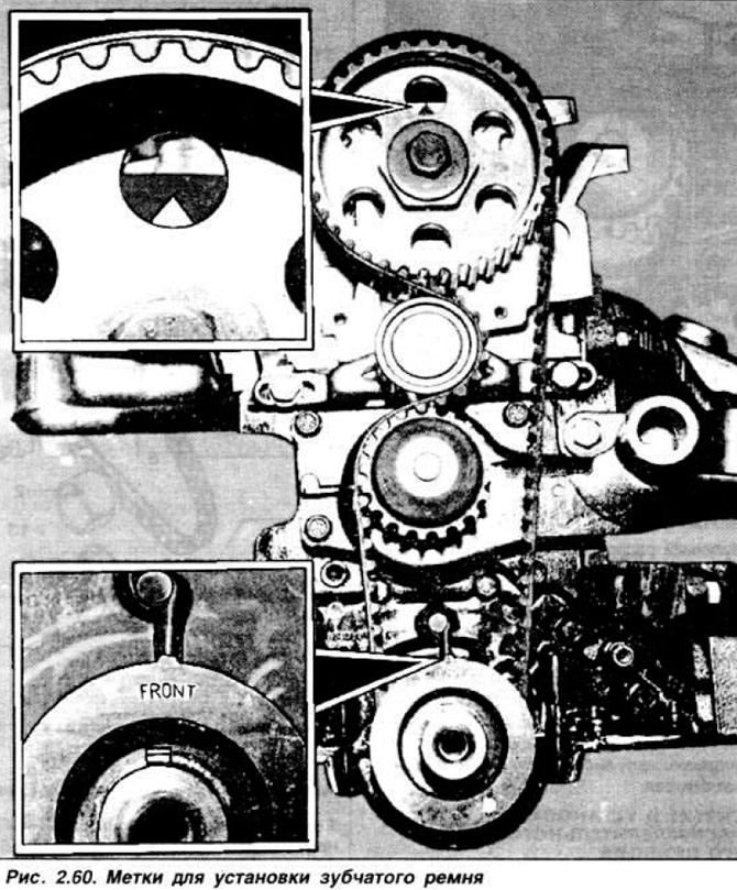
Turning the crankshaft, install the pulley tooth against the mark on the oil pump housing. Install the toothed belt, starting from the crankshaft pulley and continuing in a counterclockwise direction. Turn the crankshaft two turns clockwise and check the alignment of the marks on the camshaft and cylinder head.
For carbureted engines Turn the crankshaft counterclockwise by about 60°, which corresponds to three teeth of the camshaft pulley.
with your thumb, press the toothed belt with a force of approximately 6 kgf towards the water pump. In this position, the clearance «X» between the outer diameter of the water pump pulley and the teeth of the belt (pic. 2.61) should be 4-6 mm. To measure, use a drill of the appropriate diameter. If necessary, move the tensioner roller.
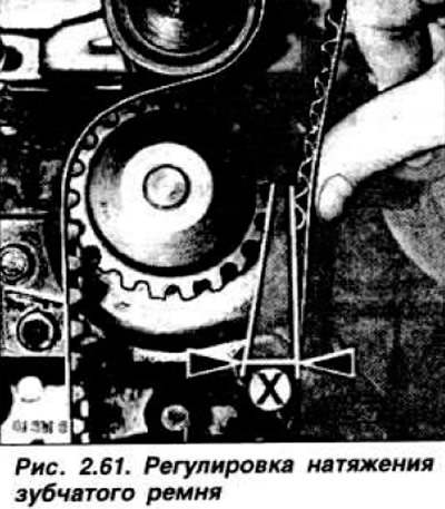
NOTE: After installing and adjusting the tension of the toothed belt, rotate the crankshaft only clockwise.
For injection engines. Tension the toothed belt by locking the crankshaft and rotating the camshaft counterclockwise using a 41 mm head and a torque wrench with a force of 4.5-5.0 kgf. Without releasing the key, tighten the tensioner mounting bolts. starting from the right bolt, with a moment of 1.6-2.0 kgf·m. Make sure. that the marks on the camshaft sprocket and cylinder head and on the crankshaft sprocket and oil pump housing are aligned.
Camshaft and its drive of the GLA engine
Cast iron camshaft 1 (pic. 2.62) mounted on three supports in the cylinder block and is driven by a single-row chain 12 from the engine crankshaft.
 Pic. 2.62. Details of the gas distribution mechanism of the GLA engine.
1 - camshaft; 2, 3 and 4 - bushings; 5 - key; 6 - thrust flange; 7 and 10 - spacers; B, 11, 14, 15 and 25 - bolts; 9 - asterisk; 12 - chain; 13 - chain tensioner assembly with eccentric and spring; 16 - elastic washer; 17 - chain tensioner shoe; 18 - shoe axis; 19 - pusher; 20 - rod; 21 - rocker; 22 - adjusting screw; 23 - rocker axis support; 24 and 29 - washers; 26 - spacer spring; 27 - the axis of the rocker arms; 28 - plug axle rocker; 30 - spring; 31 - cotter pin; 32 - crackers; 33 - spring plate; 34 - valve spring; 35 - oil cap; 36 - inlet valve; 37 - exhaust valve.
The sprockets have index marks. The camshaft is held from axial movement by a thrust flange 6, which is attached to the cylinder block with two bolts. The chain tension is provided by a spiral spring that presses the eccentric to the tensioner shoe 20.
Removal and installation of a camshaft and its drive
Due to the fact that work on the camshaft is possible only after removing the engine, the procedure for removing and installing the camshaft is described in section «Disassembly and assembly of the GLA engine».
Visitor comments