DOHC Engine Cylinder Head Assembly
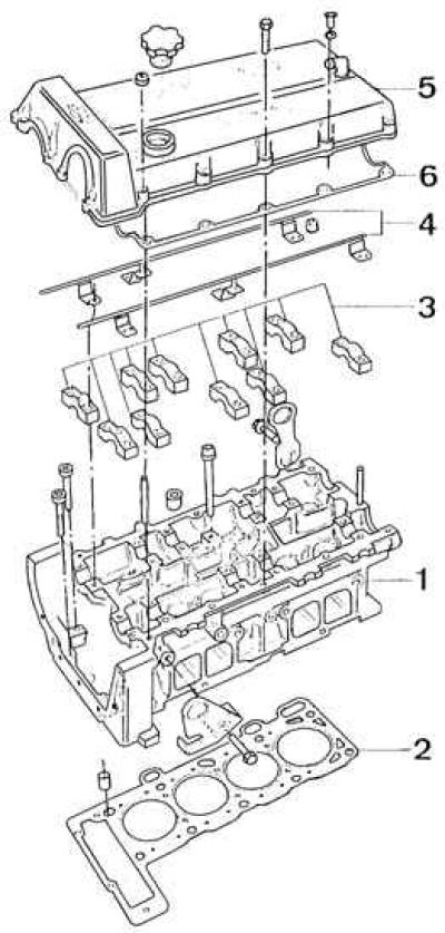
1 - cylinder head, 2 - cylinder head gasket, 3 - camshaft bearing caps, 4 - oil supply pipes, 5 - cylinder head cover, 6 - cylinder head cover gasket
Removing the cylinder head
1. Disconnect ground wire from battery.
2. Remove the air filter together with its pipes.
3. Drain the cooling system by unscrewing the bolt on the lower right side of the radiator.
4. Disconnect the upper flexible pipe from the radiator, the pipe from the expansion tank and the pipe from the thermostat.
5. Disconnect the vehicle interior heating flex pipe from the cylinder head.
6. Disconnect the bleed lines from the cylinder head cover.
7. Disconnect the accelerator pedal cable. In a carbureted engine, unscrew the throttle cable together with the holder, and in a fuel-injected engine, disconnect the link from the throttle body after removing it from the side of the clip made of artificial material.
8. On engines with fuel injection, disconnect the vacuum line from the intake manifold.
9. On fuel injected engines, disconnect the fuel supply lines to the pressure regulator and to the injectors.
10. Disconnect the high voltage wire from the ignition coil.
11. Unscrew the top nut securing the front exhaust pipe to the exhaust manifold.
12. Raise the car.
13. Unscrew the remaining two nuts securing the front exhaust pipe to the exhaust manifold.
14. Lower the car.
15. Unscrew the high voltage wires from the spark plugs and remove the ignition distributor cap (wrench Torx T25).
16. Unscrew the spark plugs.
17. Remove ignition distributor.
18. Remove cylinder head cover (11 bolts and 4 nuts).
19. Remove the upper casing of the universal joint chain of the gas distribution system.
20. Unscrew the two Torx bolts securing the camshaft sprockets.
21. Set the piston of the 1st cylinder to TDC.
22. Mark with a scriber the relative position of the sprocket tooth and the chain interacting with it.
23. Remove the top chain guide.
24. Remove the tensioner pin retainer and chain tensioner (see fig. DOHC Engine Timing Installation).
25. Remove the axle of the chain tensioner using the M6x70 bolt and a 15 mm long sleeve.
26. Remove the chain tensioner.
27. Remove sprockets from both camshafts.
28. Remove the tensioner hydraulic tappet.
29. Remove the camshaft bearing caps by gradually unscrewing the bearing caps and the oil feed line alternately.
Attention! Bearing caps are marked at the factory so that they are installed in the correct places during assembly.
30. Remove distributors.
31. Remove the hydraulic tappets and mark them in such a way that they fit into place during assembly.
32. Loosen the cylinder head bolts half a turn in the reverse order to tightening them (see fig. DOHC cylinder head bolt tightening sequence), and then unscrew the cylinder head bolts.
Attention! The bolts must not be used again to secure the cylinder head.
33. Remove the cylinder head along with the intake and exhaust manifolds. After removal from the cylinder block, the head must not be laid on the lower surface.
DOHC cylinder head bolt tightening sequence
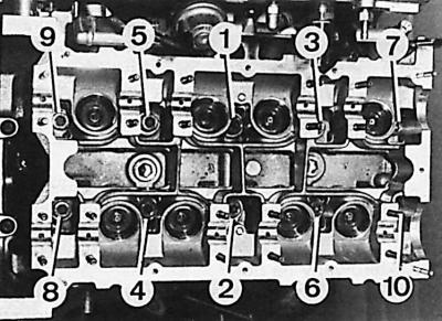
M11 bolts - tightening sequence: 1 - 10.
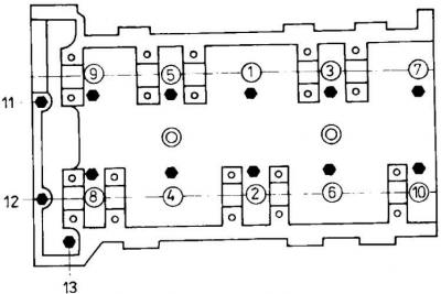
M8 bolts - tightening sequence: 11 - 13.
Installing the cylinder head
1. Clean the gasket contact surfaces on the cylinder head and engine block.
2. Install a new head gasket to the cylinder block.
3. To eliminate the possibility of damage to the valves and pistons, by rotating the crankshaft, set the piston of the 1st cylinder to a position of about 20 mm below TDC.
4. Install the head to the engine block.
5. Screw the bolts into the holes in the cylinder head by hand (see fig. DOHC cylinder head bolt tightening sequence).
6. Tighten the bolts in the sequence shown in fig. DOHC cylinder head bolt tightening sequence, in five stages:
- 1st stage (M11 bolts - sequence 1 - 10): 25 Nm;
- 2nd stage (M11 bolts - sequence 1 - 10): 55 Nm;
- 3rd stage (M11 bolts - sequence 1 - 10): tighten by 90°;
- 4th stage (M11 bolts - sequence 1 - 10): tighten by 90°;
- 5th stage (M8 bolts - sequence 11 - 13): 24–27 Nm.
Attention! Two long M8 bolts are screwed into the holes marked as (11) And (12), and a short M8 bolt into the hole (13).
7. Lubricate the surfaces of the hydraulic tappets with a thin layer of oil and install them in their respective positions in the sockets of the cylinder head.
8. Lubricate the sliding surfaces of the camshaft bearings on the cylinder head and fit the camshafts on them so that the keyways on the front side point to the right.
9. Put on the bearing caps, paying attention to their designations:
- R1-R5 - intake valve shaft bearing caps (R1 - from the drive side of the gas distribution system);
- L1–L5 - exhaust valve shaft bearing caps (L1 - from the drive side of the gas distribution system).
10. Insert the oil supply pipes to the cams and the upper propeller chain guide of the timing chain.
11. Tighten the camshaft bearing cap bolts to the appropriate torque alternately in the order corresponding to their numbers.
12. Disassemble the tensioner hydraulic tappet and drain the oil from it.
13. Using special tool 21.145, assemble the hydraulic tensioner tappet filled with engine oil. To do this, install the pusher housing with the flat side on the workbench, and on it the bushing of the device with the cone up. Install the pusher piston on the bushing and squeeze everything together with the tool lever, which makes a characteristic sound after it is pressed all the way (in the lowest position).
14. Position the hydraulic pusher of the chain tensioner in the guide.
15. Install the chain tensioner and its circlip.
16. Check if the piston of the 1st cylinder is at TDC (crankshaft keyway groove downwards).
17. Put on the two camshaft sprockets together with the chain, observing the correct relative positions in accordance with the signs made during the removal of the sprockets.
18. Perform several revolutions of the crankshaft in the direction of its working rotation, and then check the correct relative position of the shafts and the chain.
19. Install the top rail together with the mounting spring clip.
20. Install the timing chain top cover with a new gasket.
21. Install the cylinder head cover with a new gasket.
22. Tighten the cylinder head cover bolts to the appropriate torque, starting from the outer bolts and ending at the middle ones.
23. Screw in the spark plugs.
24. Install the ignition distributor, rotor and distributor cap.
25. Connect high voltage wires to spark plugs and ignition coil.
26. Screw the front exhaust pipe to the exhaust manifold with a new gasket.
27. Connect the wires to the radiator fan motors and the wiring harness to the electronic control unit.
28. On a fuel injected engine, connect the fuel lines to the pressure regulator and injectors.
29. Connect vacuum lines.
30. Connect the accelerator pedal cable.
31. Connect the bleed pipes to the cylinder head cover.
32. Connect the flexible hose for heating the passenger compartment to the cylinder head.
33. Connect the upper flexible pipe to the radiator, pipes to the expansion tank and thermostat.
34. Install the air filter.
35. Top up the amount of oil in the engine lubrication system and fill the cooling system with the appropriate liquid and remove air from it.
36. Connect ground wire to battery.
37. Check engine idle settings.
Repair of valve seats and valves
1. If the measurement results show that after grinding the valve face will meet the requirements, then they can be repaired in a specialized repair shop. In this case it is also necessary to order regrinding of the relevant valve seats.
2. Check the condition of the working chamfer of the valves.
3. Check the condition of the working chamfer of the valve seats.
4. Check the tightness of the valve-seat assembly.
5. Very carefully clean the cylinder head after grinding the seats and lapping the valves from particles of abrasive material and metal filings.
Assembly
1. Lubricate the valve stems with oil.
2. Insert the valve into the guide in which it worked before, seal the grooves at the end of the valve stem with adhesive tape.
3. Install the lower valve spring seat.
4. Lubricate the sealing lip of the valve stem seal with oil and insert it using the appropriate mounting sleeve.
5. Remove adhesive tape.
6. Repeat the last four steps for the rest of the valves.
7. Install each valve in turn with the appropriate springs, the upper spring bearing plates and crackers using a valve spring compressor.
8. Screw the intake and exhaust manifolds to the cylinder head.
Visitor comments