Contents: Removal ↳ Installation ↳
Shafts and gears of the mechanical gearbox type MT 75
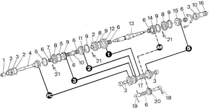
1 – needle bearing, 2 – snap ring, 3 – bearing, 4 – primary shaft, 5 – synchronizer ring, 6 – needle bearing, 7 – snap ring, 8 – 3rd–4th gear synchronizer hub, 9 – 3rd gear pinion, 10 – spacer sleeve, 11 – 2nd gear pinion, 12 – 1st gear pinion, 13 – secondary shaft, 14 – reverse gear pinion, 15 – 5th gear pinion, 16 – speedometer drive pinion, 17 – intermediate shaft, 18 – reverse gear intermediate gear shaft, 19 – reverse gear pinion bearing support sleeve, 20 – reverse gear intermediate gear, 21 – synchronizer latch
The black circles show the gear numbers (AR – reverse gear, RS – direct gear – 4)
Removal
1. Disconnect the ground wire from the battery.
2. Remove the gear shift knob.
3. Remove (depending on the equipment version) the middle console or the shelf near the gear shift lever.
4. Remove the outer gearshift lever cover after disconnecting it from the holder, and the inner cover with the holder after unscrewing the holder frame from the floor tunnel.
5. Unscrew the gear shift lever from the rear of the gearbox housing.
6. Support the clutch pedal.
7. In the engine compartment, remove the front left and right acoustic insulation.
8. Remove the upper radiator shroud.
9. Unscrew the upper starter mounting bolt and disconnect the ground wire.
10. Support the engine with a jack.
11. Remove the lower engine acoustic casing from underneath the vehicle.
12. Disconnect the metal-rubber connector from the longitudinal beam.
13. Disconnect the front intake pipe from the exhaust manifold by unscrewing the nuts that secure it.
14. Disconnect the propeller shaft from the flange of the main gear pinion, holding the studs with a Torx tool so that they do not unscrew from the flange of the main gear when unscrewing the shaft mounting nuts, and also disconnect the middle bearing of the propeller shaft from the body bracket.
15. Disconnect the ball joint of the cardan shaft from the gearbox flange and remove the cardan shaft.
16. Support the gearbox with wooden blocks.
17. Remove the gearbox mount bracket.
18. Lower the gearbox.
19. Lower the engine. Its cylinder head should not contact the brake pipes. If necessary, you can install a wooden block between the cylinder head and the front bulkhead.
20. Disconnect the outer gear shift mechanism.
21. Disconnect the speedometer cable and the wire from the reverse light switch.
22. Remove the spring clip and disconnect the clutch cable from the clutch release forks.
23. Remove the clutch housing bulkhead sheet metal, located between the engine cylinder block and the gearbox.
24. Unscrew the remaining two starter mounting bolts and remove the starter.
25. Unscrew the 3 bolts securing the clutch housing to the engine cylinder block.
26. Disconnect the gearbox from the engine and remove it from underneath the vehicle.
Installation
1. Pull the clutch release forks back and secure them in this position with wire.
2. Apply a thin layer of Ford special grease (N 5021439) to the splines of the input shaft.
3. Attach the gearbox to the engine block (3 bolts).
4. Insert two starter mounting bolts into the holes.
5. Install a sheet metal partition between the engine cylinder block and the gearbox housing.
6. Tighten the sheet metal partition mounting bolts.
7. Then perform the actions in the reverse order in relation to the process of removing the gearbox, paying attention to:
- compliance with the required tightening torques for threaded connections;
- filling the gearbox with the required amount of appropriate oil;
- checking the tightness of the gearbox.
Caution! Before installing the rubber flexible joint of the cardan shaft on the flange of the gearbox, check whether the studs are correctly secured to the flange. If it is found that the studs are turning, they must be unscrewed, cleaned, apply two drops of a product preventing unscrewing (for example, Loctite 270) to the section of the thread screwed into the flange, tighten these bolts after 5 minutes with a torque of 80 Nm and wait 30 minutes for the protective product to harden.