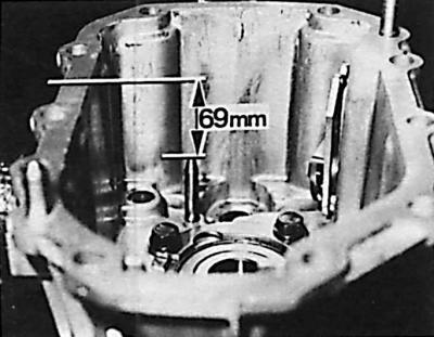
Control dimension of the selector end position
Bearing replacement
1. Using an inertial puller, remove the bearing (3) (see Fig. Shafts and gears of the mechanical gearbox type MT 75) secondary shaft from the gearbox housing.
2. Remove the secondary shaft bearing mounting plate from the gearbox housing.
3. Using a bushing of the appropriate diameter, knock out the secondary shaft ball bearing into the gearbox housing.
4. Remove the 1-2 gear fork axle from the gearbox housing.
5. Remove the sealing ring from the selector main shaft.
6. Using a bushing of the appropriate diameter, remove the needle bearing of the selector main shaft from the gearbox housing.
Attention! In case of replacement of the gearbox housing, the selector should be positioned so that the distance between its end and the housing plane (see Fig. Control dimension of the selector end position) is 69 mm.
7. Using a rod of the appropriate diameter, install a new needle bearing for the selector main shaft from inside the gearbox housing.
8. Install a new selector main shaft seal ring into the gearbox housing.
9. Position the selector shaft in the gearbox housing so that its rolled part is directed towards the sealing plane of the housing.
10. Using a suitable rod, press the intermediate shaft needle bearing into the gearbox housing until it stops.
11. Using a suitable rod, press the secondary shaft ball bearing into the gearbox housing until it stops.
12. Install the secondary shaft bearing mounting plate into the gearbox housing and tighten the bolts to the appropriate torque.
13. Using a bushing of the appropriate size, remove the ball bearing from the input shaft towards the front of the clutch housing.
14. Remove the needle bearing snap ring.
15. Using a bushing and a wooden hammer, knock the bearing off the intermediate shaft towards the rear of the clutch housing.
16. Using a puller, remove the selector main shaft needle bearing from the clutch housing.
17. Insert the intermediate shaft bearing into the clutch housing using a rod. Do not install the bearing all the way, but leave a distance of 2 mm from the plane of the clutch housing flange.
18. Install a new ball bearing snap ring.
19. Using a bushing, install a new primary shaft bearing into the clutch housing.
Checking the reverse gear pinion shaft
1. Using a suitable rod, remove the reverse gear pinion axle mounting pin.
2. Remove the bearing support sleeve, reverse gear idler gear and needle bearing from the axle.
3. Check the status of the extracted elements.
4. Place the needle bearing, reverse gear idler gear and bearing support sleeve onto the axle.
5. Install a new dowel pin.
6. Using a screwdriver, remove the sealing ring from the release bearing guide sleeve.
7. Install a new sealing ring using a rod of the appropriate diameter; the sealing edge must be directed towards the rod.
Primary and secondary shafts
Removal
1. Disconnect the primary and secondary shafts.
2. Remove the 4th gear synchronizer ring and bearing.
3. Remove the 5th gear gear, synchronizer ring and needle bearing from the secondary shaft.
4. Remove the 3-4 gear synchronizer installation spring ring from the other end of the secondary shaft.
 |
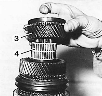 |
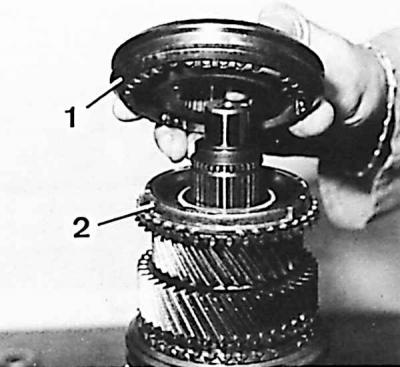
5. Remove the unit from the secondary shaft: synchronizer (1) 3-4 gears, ring (2) synchronizer 3rd gear, gear (3) 3rd gear and needle bearing (4).
Caution! Do not disassemble the synchronizers to maintain the correct position of all their parts.
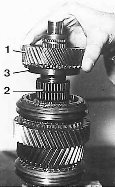
6. Remove the 2nd gear pinion (1), needle bearing (2) and 2nd gear synchronizer ring (3) from the secondary shaft.
7. Turn the secondary shaft and remove the 5th gear and reverse gear synchronizer spring ring.
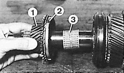
8. Remove the 5th gear gears (1), 5th gear synchronizer rings (2) and needle bearing (3) from the secondary shaft.
Examination
1. The teeth of the gears and synchronizers must not be chipped or excessively worn, and the surfaces of the teeth must not show any signs of scoring.
2. It is necessary to check whether the synchronizer hubs are chipped and whether they move without excessive gaps or jamming.
3. The needle bearing should be replaced if there are obvious scratches on the surface or if there are excessive clearances or signs of wear.
Assembly
Attention! The synchronizers of 1-2 gears and 5th and reverse gears are identical, but they cannot be interchanged when assembling the gearbox. When assembling, lubricate all components, especially the synchronizer rings and needle bearing with oil used for the gearbox.
1. Install the needle bearing and reverse gear gear on the secondary shaft.
2. Install the synchronizer ring and the 5th and reverse gear synchronizer.
3. Install a new snap ring.
4. Turn the secondary shaft and install the needle bearing and 1st gear.
5. Install the 1st gear synchronizer ring, 1-2 gear synchronizer and new snap ring.
6. Install the 1st gear synchronizer ring, needle bearing and 2nd gear.
7. Heat the 3rd gear needle bearing ring to 100°C.
8. Place the hot ring on the secondary shaft.
Caution! The needle bearing ring must be inserted deep enough to stop. A new needle bearing must be used during installation.
9. After the ring has cooled, install the needle bearing and 3rd gear.
10. Insert the 3-4 synchronizer assembly (shorter side up) and new snap ring.
11. Turn the shaft and install the 5th gear synchronizer ring, needle bearing and 5th gear.
12. Install the 4th gear synchronizer ring and bearing.
13. Connect the secondary and primary shafts.
14. Lower bolts securing the clutch housing to the cylinder block.
[The article was taken in its entirety from the specified website: FordBook]