DOHC gas distribution system
1 - intake camshaft, 2 - exhaust camshaft, 3 - intake valve, 4 - exhaust valve, 5 - valve seats, 6 - valve stem seals 7 - valve springs, 8 - upper support plates of valve springs, 9 - valve cotters, 10 - hydraulic tappets, 11 - camshaft sprockets, 12 - timing chain, 13 - oil pump drive chain, 14 - crankshaft sprocket, 15 - oil pump sprocket, 16 - crankshaft, 17 - timing chain tensioner arm, 18 - hydraulic tensioner of the cardan chain of the gas distribution system, 19 - sealing ring of the crankshaft, 20 - segmented key
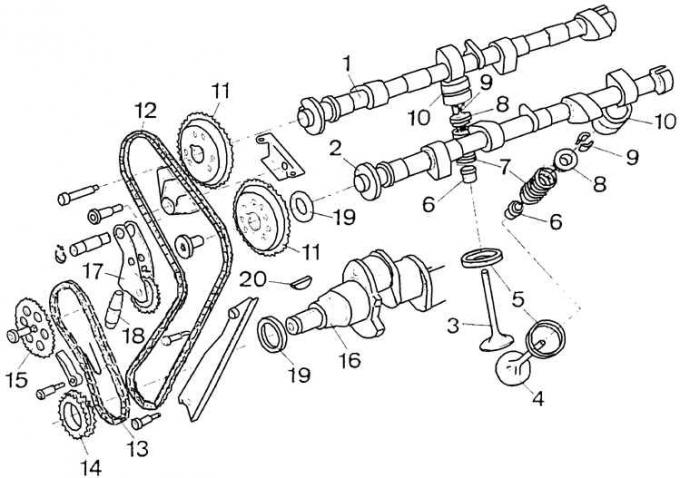
Removing the axis of the tensioner of the cardan chain of the DOHC engine gas distribution system
Removing the retaining ring.
Removing the axle of the tensioner.
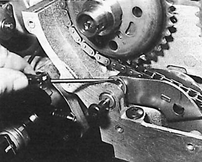
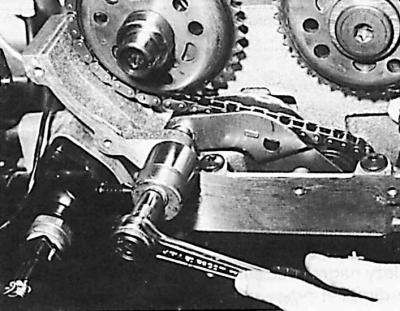
Location of the hydraulic pusher of the tensioner of the drive chain of the DOHC engine timing system
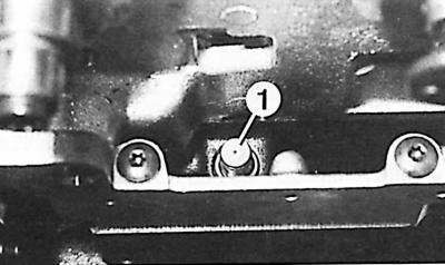
1 - hydraulic pusher
DOHC Engine Timing Installation

Camshaft setting marks.
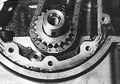
Crankshaft markings.
Replacing the cardan chain of the gas distribution system
1. Disconnect ground wire from battery.
2. Remove the alternator drive and coolant pump V-belt.
3. In a carbureted engine, remove the air filter.
4. On the fuel injected version, remove the air supply line from the filter to the throttle body.
5. Remove the high voltage wires, unscrew the spark plugs, the ignition distributor cap and the distributor rotor.
6. Disconnect the crankcase breather pipe from the cylinder head cover.
7. Disconnect the accelerator pedal cable. In the engine carburetor, unscrew the throttle cable together with the holder, and in the engine with fuel injection, disconnect the link from the throttle body after removing it from the side of the clip made of artificial material.
8. Remove cylinder head cover (11 bolts and 4 nuts).
9. Remove the ignition distributor.
10. Remove the upper casing of the universal joint chain of the gas distribution system.
11. Set the piston in cylinder N1 to TDC.
Attention! It is possible to turn the crankshaft with a ring spanner by the middle bolt of the sprocket in the direction of its working rotation until the signs on the camshaft sprockets are at the height of the upper plane of the cylinder head and are directed outward in both camshafts.
12. Unscrew the nut securing the crankshaft sprocket.
13. Using a puller, remove the sprocket from the crankshaft. If necessary, remove the radiator.
14. Remove the lower casing of the propeller chain of the gas distribution system.
15. Remove the oil pump propeller chain tensioner.
16. Unscrew the Torx bolt securing the oil pump drive sprocket and remove the sprocket together with the chain.
17. Remove, held by a spring hook, the upper propeller chain guide of the gas distribution system.
18. Unscrew the upper and lower bolts of the side guide of the propeller chain of the gas distribution system.
19. Remove the retaining ring of the tensioner, and then remove the tensioner of the universal joint chain of the timing chain.
20. Remove the axle of the chain tensioner using the M6Ch70 bolt and a 15 mm long sleeve.
21. Remove sprockets from both camshafts. Mark them in order to put them in the appropriate places during the assembly process.
22. Pull up the side chain guide.
23. Remove the sprocket from the crankshaft.
24. Pull up the timing chain.
25. Remove the chain tensioner.
26. Remove the chain tensioner hydraulic pusher.
Attention! After removing the cardan chain, the crankshaft must not be turned.
27. Disassemble the tensioner hydraulic tappet and drain the oil.
28. Using special tool 21.145, assemble the hydraulic tensioner tappet filled with engine oil. To do this, install the pusher body with the flat side on the workbench, and on it the fixture sleeve with the cone up. Install the pusher piston on the bushing and squeeze everything together with the tool lever, which makes a characteristic sound after it is pressed all the way (in the lowest position).
29. Check if the piston of the 1st cylinder is at TDC (crankshaft groove pointing down).
30. Put the chain on the crankshaft. Check the correct connection to the crankshaft.
31. Install side chain guide.
32. Install the chain tensioner hydraulic pusher.
33. Install the chain tensioner.
34. Insert the chain tensioner together with the circlip.
35. Set the camshafts to the position shown in fig. Installing a DOHC engine timing - the keyways of both shafts must be directed horizontally outward of the cylinder head.
36. Fit the timing chain to the camshaft sprockets.
37. Install the sprockets together with the chain on the camshafts so that the marked chain link is opposite the sign on the crankshaft sprocket (see bottom of fig. DOHC Engine Timing Installation).
Attention! When installing the sprockets, the drive chain must be tensioned on the opposite side of the tensioner.
38. On the front end of the intake camshaft, put on the elements of the ignition distributor drive.
39. Rotate the crankshaft a few revolutions (in working direction).
40. Set the piston in cylinder N1 to TDC and check that the camshaft sprocket keyways are installed horizontally outside the cylinder head (pic. DOHC Engine Timing Installation).
41. Install the top chain guide.
42. Slide the oil pump drive chain onto the sprocket on the crankshaft, and then install the sprocket (with a chain on it) on the oil pump shaft, making sure that the inscription "FRONT" on the asterisk was on the outside (was visible).
43. Install the oil pump propeller chain tensioner.
44. Set the groove of the sprocket to match the groove of the crankshaft.
45. Install the lower casing of the universal joint chain of the timing system together with a new gasket, screw in the bolts of its fastening, but do not tighten them.
46. Slide the pulley onto the crankshaft and tighten its fastening nut to the appropriate torque.
47. Tighten the bolts of the lower casing of the propeller chain of the gas distribution system to the appropriate torque.
48. Carry out the following steps in reverse order with respect to the removal process, paying attention to:
- installation of a new gasket for the upper casing of the cardan chain of the gas distribution system;
- the correct sequence of tightening the bolts of the cylinder head cover, starting with the extreme ones, and ending with the middle ones;
- observance of the necessary tightening torques of the corresponding threaded connections;
- filling with liquid and removing air from the engine cooling system after installation is completed;
- checking engine idle control parameters.
Visitor comments