General description
1. Electronic engine control system (EEC - IV) consists of an on-board computer known as the Electronic Control Unit (ECA) and information sensors that take engine data and output data to the ECA. In turn, the ECA, based on the information received from the sensors and the program embedded in the computer, produces various signals (teams) to control the operation of the engine.
2. ECA is "brain" EEC - IV system, it is located inside the dashboard (behind the glove box, above the recirculation line). It receives data from a number of sensors and other electronic components (switches, relays, etc.), based on the information received. ECA generates output signals to control various relays, solenoids and other actuators (see below). ECA is specifically designed to optimize emissions, save fuel and improve your vehicle's handling.
Information input sensors
3. Some engines are equipped with a knock sensor (see picture), which give a signal to the ECA about the appearance of detonation, prompting the system to change the ignition timing.

4. When battery voltage hits the A/C compressor clutch, a signal is sent to the ECA, which perceives it as an additional load and increases the idle speed of the engine to compensate.
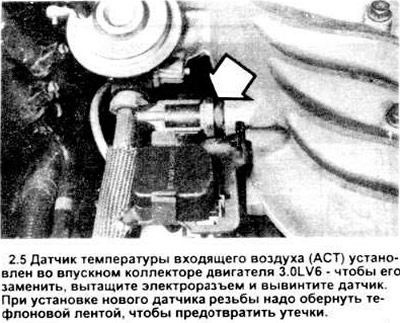
5. Inlet air temperature sensor (ACT) screwed into the intake manifold guide (see picture), provides the ECA with information about the temperature of the air-fuel mixture The ECA uses this information to adjust the fuel delivery and control the delivery during the cold start process.
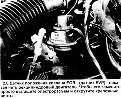
6. EGR valve position sensor (EVP), located on the EGR valve itself (see picture), gives information to the ECA about the position of the EGR valve.
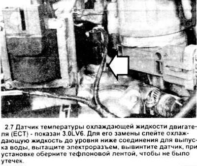
7. Engine coolant temperature sensor (EATING), located next to the water outlet (see picture), monitors engine coolant temperature The ECT sends a constantly changing signal to the ECA that affects the ECA system's control of the fuel mixture, ignition timing and EGR operation.
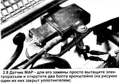
8. Manifold absolute pressure sensor (IDA), mounted on a fire wall (see picture), measures the absolute value of the mixture pressure in the intake manifold and sends an ECA signal.
9. Oxygen sensor (EGO), screwed into the exhaust manifold (see picture), constantly records the oxygen content in the exhaust gases. A signal is sent to the ECA system depending on the difference in the oxygen content in the exhaust gases and the surrounding atmosphere. ECA calculates the ideal ratio for the current operating conditions of the engine.
10. Crankshaft position and speed sensor (PIP) made in the same housing with the distributor, informs the ECA about the position and speed of the crankshaft. The PIP assembly consists of a four-window, four-reed armature that rotates behind the stator assembly (Hall Sensor).
11. Throttle position sensor (TPS), mounted on the side of the throttle body (see picture) and is directly connected to the throttle shaft, it detects the movement and position of the throttle and transmits the ECA signal.

12. Electronic converter of values for feeding the pressure of the EGR system - (PFE) converts the exhaust pressure value signal into a voltage proportional to it, processed by the EEC - IV processor. The EEC - IV processor uses the signal from the PFE converter in order to calculate the optimum flow through the EGR.
External devices
13. The control relay assembly, controlled by the ECA, generates an external signal that controls the operation of the air conditioning compressor clutch, electric fan and fuel pump.
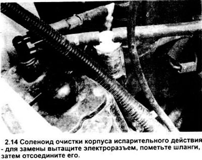
14. Housing cleaning solenoid (CANP) located in the recess of the left wing (see picture), when receiving a signal from the ECA, it turns on / off the vacuum in the manifold, thereby activating the housing cleaning valve. When the solenoid is connected, the vacuum opens the purge valve.
15. The solenoid that controls the EGR system, located in the right rear corner of the engine compartment, at the command of the ECA, switches the vacuum in the manifold, thus acting on the EGR valve. When voltage is applied to the solenoid, the vacuum opens the EGR valve.
16. Solenoid - EGR switch - an electrical vacuum valve located between the manifold vacuum source and the EGR valve. A controlled vacuum tap is located between the solenoid and the EGR valve. This vacuum outlet is called a back pressure change converter (BVT). These two devices optimize the operation of the EGR valve. The housing cleaning valve is also equipped with a solenoid - a vacuum switch.
17. The EGR vent solenoid opens the EGR control solenoid vacuum line. When the vent solenoid is energized, the control solenoid opens the EGR valve.
18. The auxiliary air control solenoid, in accordance with signals from the ECA, regulates the fuel / air ratio at idle, normal engine operation and in a transient state.
19. Pre-1990 vehicles with four-cylinder engines have a single solenoid-controlled fuel injector located on the throttle body. On vehicles with V6 and four-cylinder engines, since 1991, the injectors are located in the intake manifolds. The ECA controls the length of time during which each of the injectors is open.
Time "discoveries" The injector determines the amount of fuel delivered. For information regarding the replacement of injectors, see chapter 4.
20. The fuel pump relay is activated by the ECA system when the ignition key is in the "included". When the key is turned to position "included", the relay provides the system with an initial pressure level. IN chapter 4 contains information on checking and replacing the fuel pump.
21. Engine idle speed control (ISC) (four-cylinder engines up to 1990) changes the idle speed in accordance with the signals from the ECA. Information regarding the replacement of the ISC is given in chapter 4.
22. TFI ignition module - IV, on most vehicles it is mounted at the base of the distributor - starts the ignition coil The ECA uses the signal from the crankshaft position and speed sensor to determine the position of the crankshaft. The ignition timing is determined by the ECA, after which a signal is given to the module to connect the coil. Further information regarding the TFI - IV module can be found in the relevant section chapter 5.
23. Compressor shutdown circuit at full throttle. Disconnects the compressor from the engine when the throttle is fully opened and turns it on when it is partially closed.
Examination
24. Since specialized test equipment is required to test sensors and external devices, diagnostics of the above elements is not within the purview of this publication.
Replacing elements
Inlet air temperature sensor (ACT)
25. Disconnect the wire from the negative battery terminal.
26. Locate the ACT sensor on the intake manifold (see fig. 2.5).
27. Remove the electrical connector from the sensor.
28. Unscrew the sensor with a wrench.
29. Wrap the threads of the new sensor with Teflon tape to prevent leaks.
30. Install in reverse order.
EGR valve position sensor (EVP) - for four-cylinder engine
31. Disconnect the wire from the negative battery terminal.
32. Locate the EVR sensor on the EGR valve (see figure 2.6).
33. Pull out the electrical connector of the sensor.
34. Turn off three fixing bolts and disconnect the gauge.
35. Installation is carried out in the reverse order.
Coolant temperature sensor (EATING)
36. Disconnect the wire from the negative battery terminal.
37. Locate the ECT sensor near the water outlet assembly (see figure 2.7).
38. Pull out the electrical connector of the sensor.
39. Unscrew the sensor with a wrench.
40. Wrap the threads of the new sensor with Teflon tape to prevent leaks.
41. Installation is carried out in the reverse order.
Manifold absolute pressure sensor (IDA)
42. Disconnect the wire from the negative battery terminal.
43. Locate the MAP sensor on the fire wall (see figure 2.8).
44. Pull out the electrical connector of the sensor.
45. Disconnect the vacuum pipeline from the sensor.
46. Unscrew two fixing bolts and remove the gauge.
47. Installation is carried out in the reverse order.
Exhaust Oxygen Sensor (EGO)
48. Disconnect the wire from the negative battery terminal
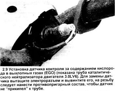
49. Raise the car, place it securely on racks. Locate the EGO sensor on the exhaust manifold (in a four-cylinder engine) or on the catalytic converter pipe (V6 engines) (see figure 2.9).
50. Disconnect the sensor electrical connector.
51. Unscrew the sensor with a wrench.
52. Apply non-stick compound to the threads of the new sensor to avoid it "welding" to the collector.
53. Installation is carried out in the reverse order.
Throttle position sensor (TPS)
54. Before replacing the TPS switch, thoroughly study this procedure (see chapter 4). Adjustment of the installed switch requires specialized calibration equipment. The description of this procedure is beyond the scope of this publication.
Housing cleaning solenoid
55. Disconnect the wire from the negative battery terminal.
56. Locate the housing cleaning solenoid on the left side of the engine compartment, next to the left wheel recess (see fig. 2.14).
57. Pull out the solenoid electrical connector.
58. Mark vacuum hoses and inputs, then disconnect hoses.
59. Remove the solenoid.
60. Installation is carried out in the reverse order.
Visitor comments