NOTE: Sensor replacement is shown on a vehicle with a Duratec Ti-VCT engine. On vehicles with other engines, the work is carried out in a similar way, although the location and number of sensors may differ.
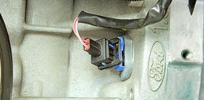
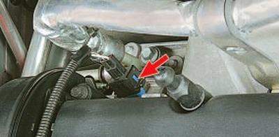
The crankshaft position sensor of the engine is mounted at the rear of the engine block opposite the flywheel.
If a malfunction occurs in the crankshaft position sensor circuit, the engine stops working, the ECU stores the fault code in memory and turns on the warning light in the instrument cluster. In this case, check that the sensor is working properly.
You will need: socket head "8", tester.
1. Disconnect a wire from the minus plug of the storage battery.
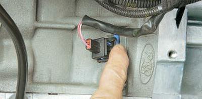
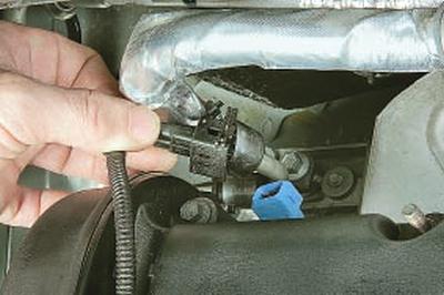
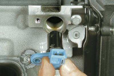
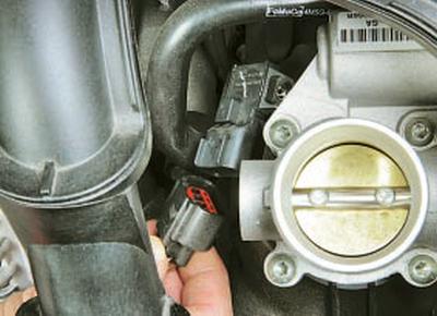
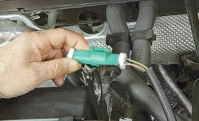
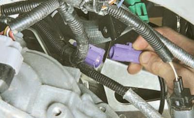
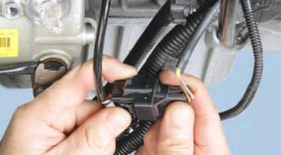
2. Squeeze the latch..
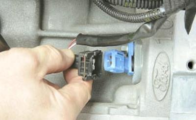
3.... and disconnect the wiring harness connector from the crankshaft position sensor terminals.
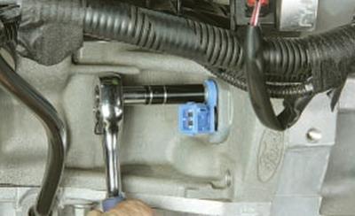
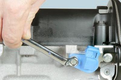
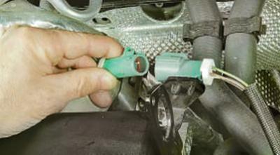
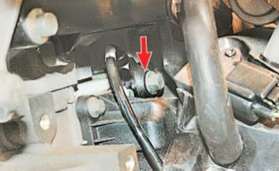
4. Turn out a bolt of fastening of the gauge …
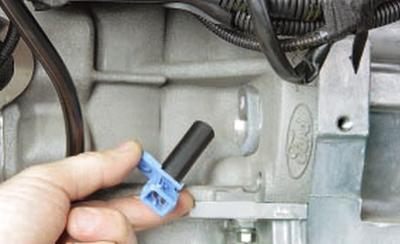
5.... and remove the sensor from the hole in the cylinder block.
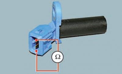
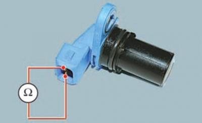
6. Using a tester, measure the resistance between the sensor leads. The nominal value of the resistance should be in the range of 0.5–0.6 kOhm. If the resistance is not within the specified limits, replace the sensor.
7. Install the engine crankshaft position sensor in the reverse order of removal.
The camshaft position sensor is mounted on top of the cylinder head. In the event of a fault in the sensor circuit, the ECU memorizes a fault code and uses a bypass control program.
You will need: a key "for 10", a tester.
1. Disconnect a wire from the minus plug of the storage battery.
2. Remove the decorative engine cover (see Removal and installation of a decorative casing of the engine).
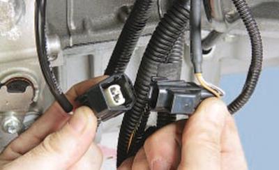
3. Compress a clamp and disconnect a block of a plait of wires from the gauge.
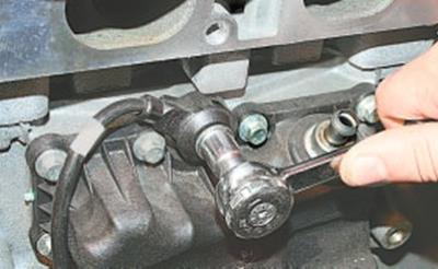
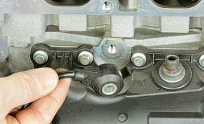
4. Turn out a bolt of fastening …
5.... and remove the sensor from the hole in the cylinder head.
6. Using a tester, measure the resistance between the sensor leads. Rated resistance 0.5–0.6 kOhm. If the resistance is not within the specified range, replace the sensor.
7. Install the camshaft position sensor in the reverse order of removal.
The coolant temperature sensor is installed in the coolant distributor housing located on the transmission side of the cylinder head. In the event of a sensor failure, the ECU memorizes a fault code and uses a bypass engine management program (calculates the approximate value of the coolant temperature from the engine running time and the absolute air pressure in the intake pipe).
Check the resistance at the sensor terminals at various temperature conditions.
You will need: key "19", tester, thermometer.
1. Disconnect a wire from the minus plug of the storage battery.
2. Drain the liquid from the engine cooling system (see Coolant Change).
USEFUL ADVICE: When replacing the sensor, the coolant may not be drained: after removing the sensor, plug the hole with a finger or a plug - the loss of coolant will be minimal.
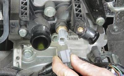
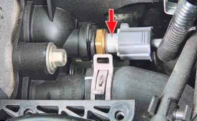
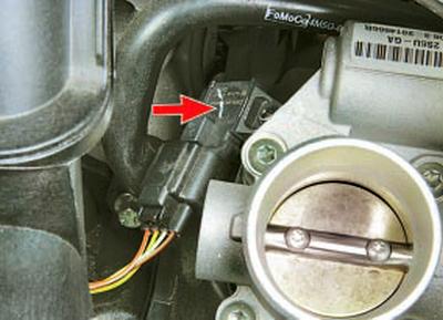
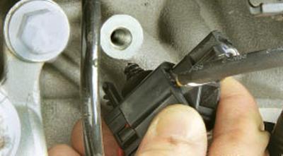
3. While pressing the latch, disconnect the wiring harness block from the coolant temperature sensor.
NOTE: For clarity of photography, the ignition coil was removed from the engine and the hoses were disconnected from the pipes of the coolant distributor.
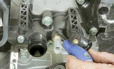
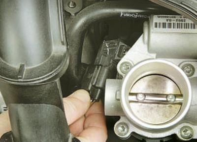
4. Pry with a screwdriver..
5….and remove the sensor spring retainer.
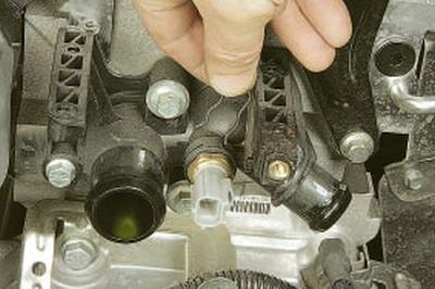
6. Remove the temperature sensor from the coolant distributor hole.
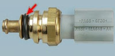
NOTE: The temperature sensor is sealed in the coolant distributor opening with a rubber ring. When installing the sensor, replace the ring with a new one.
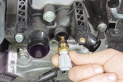
7. Connect the tester to the sensor terminals and measure the resistance, and measure the current temperature with a thermometer.
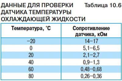
8. To measure the resistance at the sensor terminals under various temperature conditions, lower the sensor into hot water and check the change in its resistance as the water cools, controlling the water temperature with a thermometer. The nominal resistance of a good sensor is indicated in Table.
10.6. If the resistance deviates from the norm, replace the sensor.
9. Install the coolant temperature sensor in the reverse order of removal.
10. Fill in coolant.
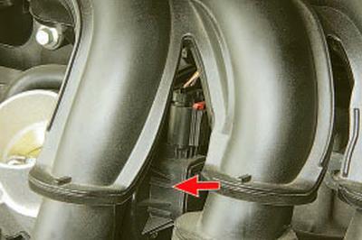
The combined absolute pressure and intake air temperature sensor is installed in the intake pipe.
In the event of a sensor malfunction, the ECU memorizes a fault code and uses a bypass engine management program (calculates approximate intake manifold absolute air pressure from engine speed and throttle position).
You will need a TORX T20 key.
1. Disconnect a wire from the minus plug of the storage battery.
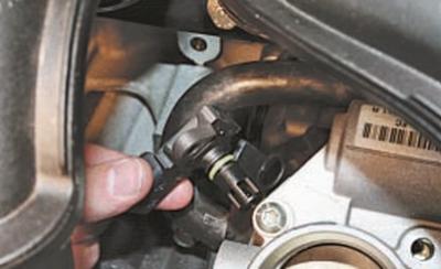
2. Press the latch..
3.... and disconnect the wiring harness block from the sensor.
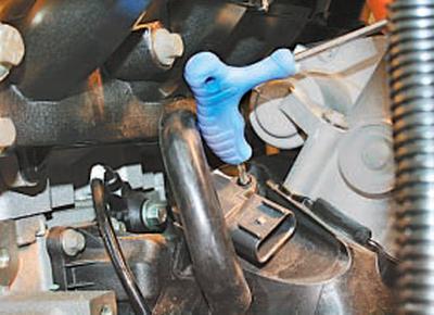
4. Turn out the screw of fastening..
5.... and remove the sensor from the intake pipe.
6. Install the new sensor in the reverse order of removal.
Throttle position sensor is built into the throttle assembly cover, so if the sensor fails, replace the throttle assembly (see Removing and installing the throttle assembly).
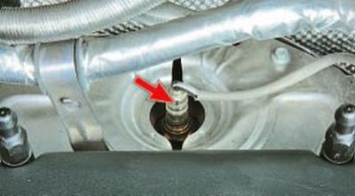
The control oxygen concentration sensor is installed in the threaded hole at the inlet to the collector. If the sensor is defective, the toxicity of the exhaust gases can increase dramatically, and fuel consumption can increase.
You will need a key "on 22"..
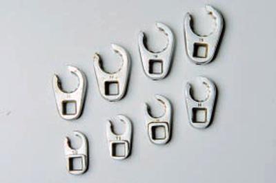
... it is more convenient to use a special split key, similar to those shown in the photo.
1. Disconnect a wire from the minus plug of the storage battery.
2. Remove the decorative engine cover (see Removal and installation of a decorative casing of the engine).
3. Squeeze the clamp of the oxygen concentration sensor harness block.
4.... and disconnect the block.
5. Remove the thermal screen of the collector (see Removing and installing thermal shields).
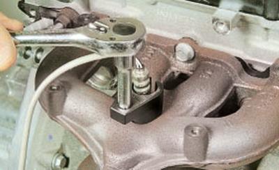
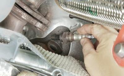
6. Install the key on the sensor, loosen the sensor..
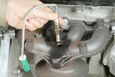
7.... and turn out the control oxygen concentration sensor.
8. Install a new oxygen concentration sensor in the reverse order of removal.
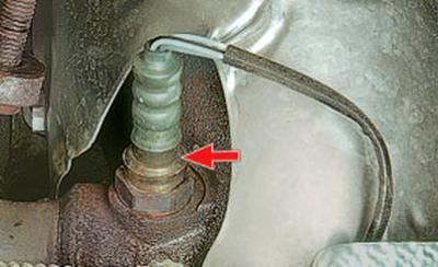
The diagnostic oxygen concentration sensor is installed in the threaded hole at the outlet of the collector. If the sensor is defective, the toxicity of the exhaust gases can increase dramatically, and fuel consumption can increase.
You will need a key "on 22" (or special split end).
1. Disconnect a wire from the minus plug of the storage battery.
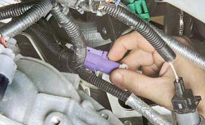
2. Squeeze the latch..
3….and disconnect the diagnostic oxygen sensor harness connector.
4. Loosen the sensor sensor and unscrew it from the collector.
5. Install the sensor in the reverse order of removal.
The knock sensor is attached to the wall of the cylinder block in its upper part under the intake manifold in the area of the 3rd cylinder. In the event of a sensor failure, the ECU memorizes a fault code and uses a bypass engine management program (with a reduced ignition timing to prevent detonation).
You will need a key "for 13".
1. Disconnect a wire from the minus plug of the storage battery.
2. Remove intake pipe (refer to Intake Pipe Gasket Replacement).
3. Disconnect the block of the wiring harness from the engine block, overcoming the clamp force.
4. Squeeze the latch..
5.... and disconnect the knock sensor wiring harness connector.
6. Turn out a bolt of fastening of the gauge of a detonation to the block of cylinders …
7….and remove the sensor.
8. Install the knock sensor in the reverse order of removal.
Visitor comments