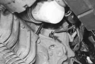
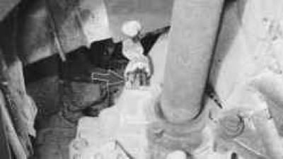
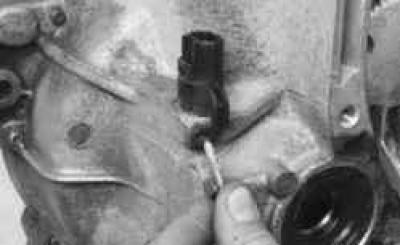
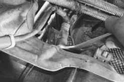
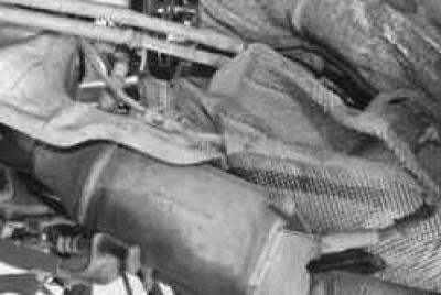
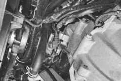
Engine Crankshaft Position Sensor installed at the rear of the engine cylinder block opposite the flywheel.
If a fault occurs in the crankshaft position sensor circuit, the engine stops running, the controller stores a fault code in memory and turns on the warning light in the instrument cluster. In this case, check the sensor for proper operation.
You will need: an 8 mm socket head and a tester.
1. Disconnect the wire from the negative terminal of the battery.
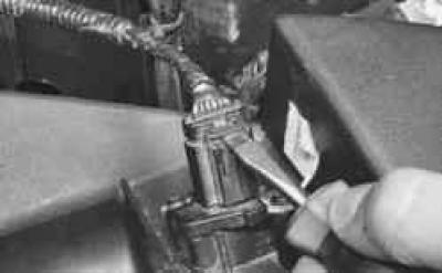
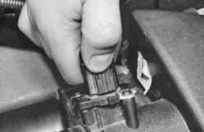
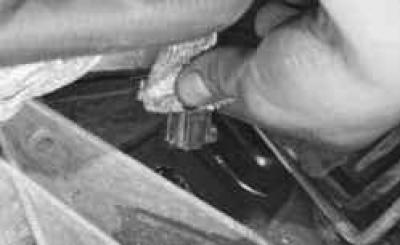
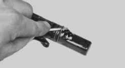
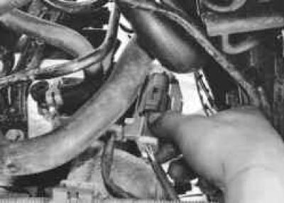
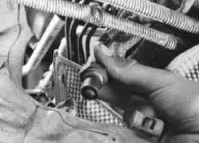
2. Squeeze the latch…

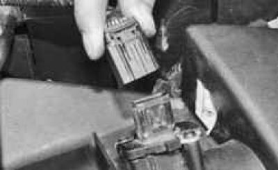
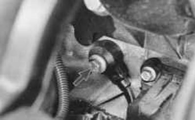
3. …and disconnect the crankshaft position sensor wiring harness connector.
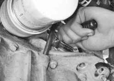
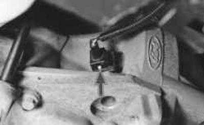
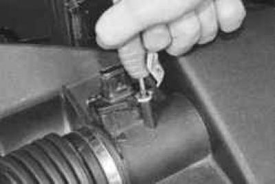
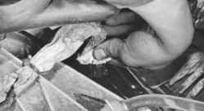
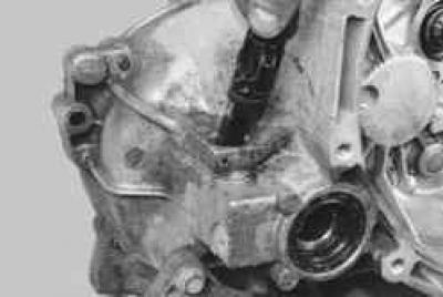
4. Unscrew the sensor mounting bolt…
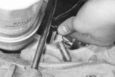
5. …and remove the sensor from the hole in the cylinder block.
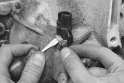
6. Measure the resistance between the sensor terminals with a tester. The nominal resistance value should be within 0.5–0.6 kOhm. If the resistance does not meet the specified limits, replace the sensor.
7. Install the engine crankshaft position sensor in the reverse order of removal.
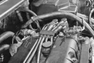
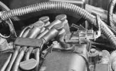
Camshaft position sensors are installed on top of the cylinder head. If there is a fault in the circuit of any sensor, the controller stores a fault code in memory and uses a bypass engine control program (without changing the valve timing).
You will need a 10 mm wrench.
1. Disconnect the wire from the negative terminal of the battery.
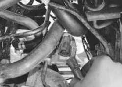
2. Squeeze the retainer and disconnect the sensor wiring harness connector.
3. Unscrew the mounting bolt and remove the sensor from the hole in the cylinder head.
4. Install the camshaft position sensor in the reverse order of removal.
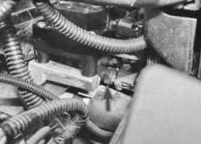
Coolant temperature sensor installed in the water jacket outlet pipe of the engine under the ignition coil.
The resistance at the sensor terminals is checked under different temperature conditions.
You will need: a 19 mm wrench, a tester, and a thermometer.
1. Disconnect the wire from the negative terminal of the battery.
2. Drain the fluid from the engine cooling system (see "Replacing the coolant").
USEFUL TIP: When replacing the sensor, you do not need to drain the coolant: after removing the sensor, plug the hole with your finger or a plug - the loss of coolant will be minimal.
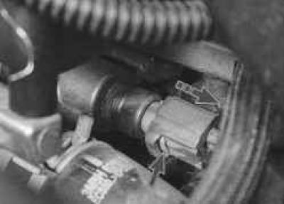
3. Press the lock, disconnect the wiring harness connector from the sensor, loosen the tightening with a wrench and unscrew the coolant temperature sensor by hand.
4. Connect the tester to the sensor terminals and measure the resistance, and measure the current temperature with a thermometer.
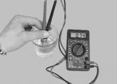
5. To measure the resistance at the sensor terminals under different temperature conditions, lower the sensor into hot water and check the change in its resistance as the water cools, monitoring the water temperature with a thermometer. The nominal resistance of a working sensor is indicated in Table 10.4.
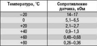
Table 10.4 Coolant Temperature Sensor Test Data
6. If the resistance deviates from the norm, replace the sensor.
7. Screw in the coolant temperature sensor and tighten it to a torque of 12 N·m.
8. Connect the wiring harness connector to the sensor.
9. Fill with coolant.
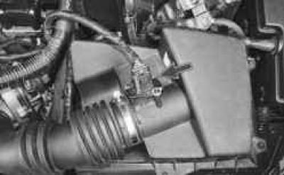
Combined mass air flow and intake air temperature sensor installed on the air filter housing cover.
You will need: TORX T20 key, flat-blade screwdriver, tester, thermometer.
1. Disconnect the wire from the negative terminal of the battery.
2. Use a screwdriver to lift up the sensor wiring harness connector retainer.
3. Squeeze the latch…
4. …and disconnect the wiring harness connector from the sensor.
5. Remove the two mounting screws…
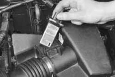
6. …and remove the mass air flow and intake air temperature sensor.
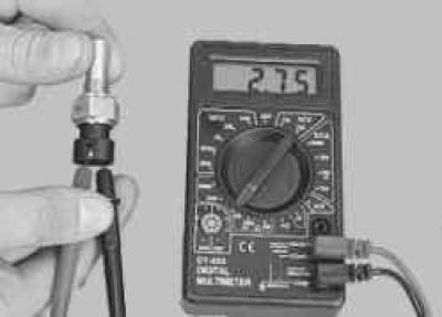
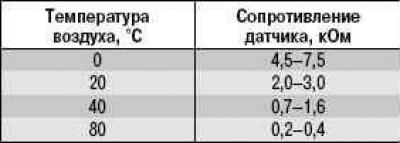
7. Connect the tester in ohmmeter mode to the sensor terminals and measure its resistance. Measure the current air temperature with a thermometer and compare the obtained values with Table 10.5.
Table 10.5 Data for checking the mass air flow and intake air temperature sensor
8. If the resistance deviates from the norm, replace the sensor.
9. Install the combined mass air flow and intake air temperature sensor in the reverse order of removal.
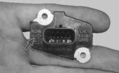
NOTE: Install the sensor in such a position that the arrow on the housing coincides with the direction of the air flow.
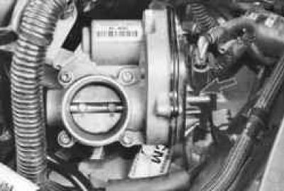
Throttle Position Sensoris a variable resistor that is mounted on the throttle shaft. Rotation of the throttle shaft causes a change in the voltage of the sensor signal, by which the controller determines the degree of opening of the throttle valve. The sensor is built into the throttle assembly cover, so if the sensor fails, replace the throttle assembly as a whole (see "Removing and installing the throttle assembly").
Vehicle speed sensor installed on the gearbox near the right front wheel drive.
You will need a flat-blade screwdriver.
1. Disconnect the wire from the negative terminal of the battery.
2. Lift up the heat shield of the speed sensor wiring harness.
3. Squeeze the retainer and disconnect the wiring harness connector from the speed sensor.
NOTE: For clarity, the following steps are shown with the gearbox removed.
4. Use a screwdriver to remove the retaining pin from the recess in the gearbox housing…
5. …and remove the locking pin.
6. Remove the speed sensor from the hole in the gearbox housing.
7. Inspect the sensor sealing ring. If there is any damage, or if there are traces of oil on the gearbox housing around the sensor, replace the ring with a new one.
8. Install the speed sensor in the reverse order of removal.
Oxygen concentration sensors installed on the catalytic converter before and after the neutralizers.
Oxygen concentration sensors at the inlet to the neutralizers are the control…
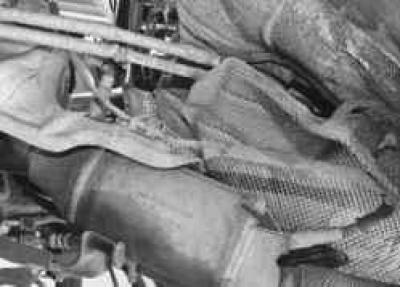
…at the exit from the neutralizers – diagnostic.
All four sensors have the same parameters and differ only in the length of the wires. If at least one of the oxygen concentration sensors is faulty, the toxicity of exhaust gases can increase sharply, and fuel consumption will increase.
For ease of replacement, the sensors are distinguished by the color of the wires and their pads. The sensors of the left neutralizer have blue wires, and the sensors of the right neutralizer have white wires. The pads of the wire harnesses of the sensors at the input to the neutralizers (control) are green, and at the output from the neutralizers (diagnostic) are blue.
You will need a 22 mm wrench.
1. Disconnect the wire from the negative terminal of the battery.
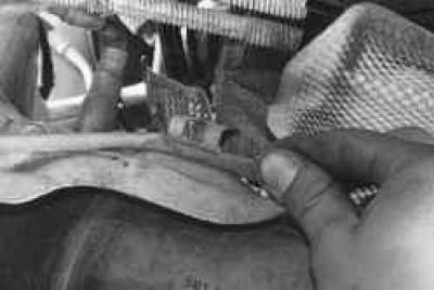
2. Squeeze the latch…
3. …and disconnect the wiring harness connector of the sensor being replaced.
4. Remove the diagnostic sensor wiring harness from the holder on the heat shield.
5. Turn the control…
6. …or diagnostic sensor…
7. …and remove it from the exhaust manifold hole.
8. Install the oxygen concentration sensor in the reverse order of removal.
NOTE: A faulty oxygen sensor can be replaced with a sensor with a longer wiring harness. In this case, it is necessary to secure the harness in such a way as to avoid its contact with hot parts of the exhaust system.
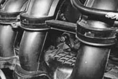
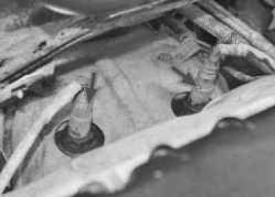
Knock sensors screwed into the wall of the cylinder block in its upper part, under the intake manifold in the areas between the 1st and 2nd, as well as between the 3rd and 4th cylinders.
You will need a 13 mm wrench.
1. Disconnect the wire from the negative terminal of the battery.
2. Disconnect the wiring harness connector of the sensor being replaced.
3. Loosen the knock sensor mounting bolt and remove the sensor.
4. Install the sensor in the reverse order of removal.
(The article was taken in its entirety from the specified website: FORDBOOK.RU)