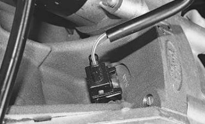
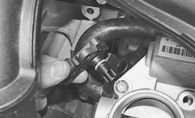
Engine crankshaft position sensor installed at the rear of the engine block opposite the flywheel.
If a malfunction occurs in the crankshaft position sensor circuit, the engine stops working, the controller stores the malfunction code in memory and turns on the signal lamp in the instrument cluster. In this case, check that the sensor is working properly.
You will need: socket head «for 8», tester.
1. Disconnect the wire from the terminal «minus» battery.
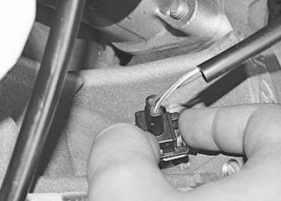
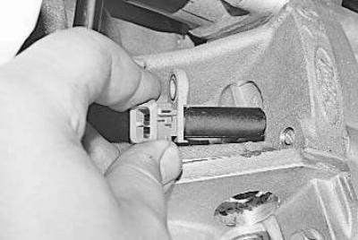
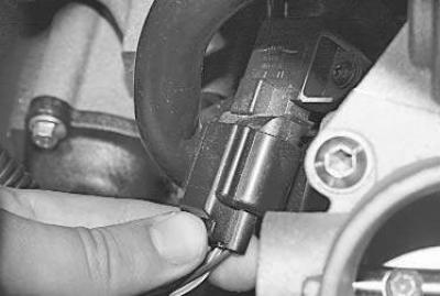
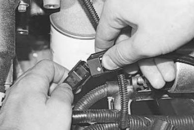
2. Squeeze the latch..
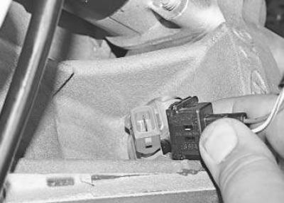
3.... and disconnect the wiring harness connector from the crankshaft position sensor terminals.
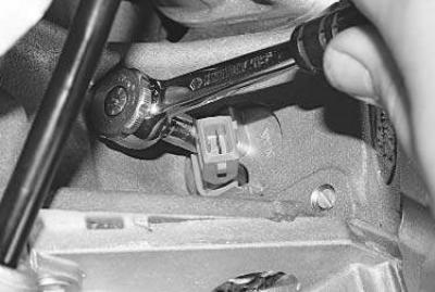
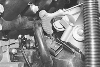
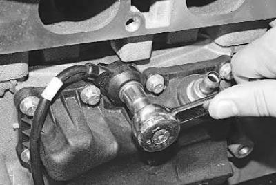
4. Turn out a bolt of fastening of the gauge …
5.... and remove the sensor from the hole in the cylinder block.
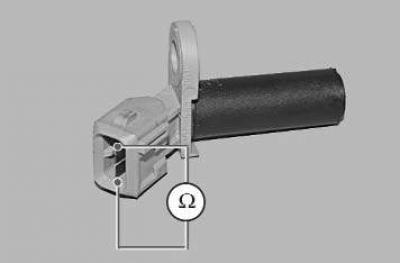
6. Using a tester, measure the resistance between the sensor leads. The nominal value of the resistance should be in the range of 0.5–0.6 kOhm. If the resistance is not within the specified limits, replace the sensor.
7. Install the engine crankshaft position sensor in the reverse order of removal.
Camshaft position sensor mounted on top of the cylinder head. In the event of a fault in the sensor circuit, the controller memorizes the fault code and uses a bypass control program.
You will need a key «on 10».
1. Disconnect the wire from the terminal «minus» battery.
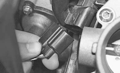
2. Squeeze the latch and disconnect the sensor harness connector.
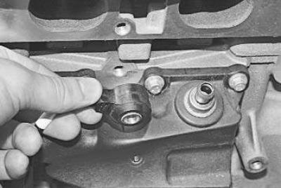
3. Turn out a bolt of fastening …
4.... and remove the sensor from the hole in the cylinder head.

5. Using a tester, measure the resistance between the sensor leads. The nominal value of the resistance should be in the range of 0.5–0.6 kOhm. If the resistance is not within the specified limits, replace the sensor.
6. Install the camshaft position sensor in the reverse order of removal.
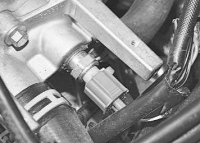
coolant temperature sensor installed in the coolant distributor housing located under the ignition coil.
Note. The ignition coil has been removed for clarity.
Check the resistance at the sensor terminals at various temperature conditions.
You will need: key «at 19», tester, thermometer.
1. Disconnect the wire from the terminal «minus» battery.
2. Drain the liquid from the engine cooling system (see «Coolant replacement»).
Note. When replacing the sensor, the coolant can not be drained: after removing the sensor, plug the hole with your finger or a plug - the loss of coolant will be minimal.
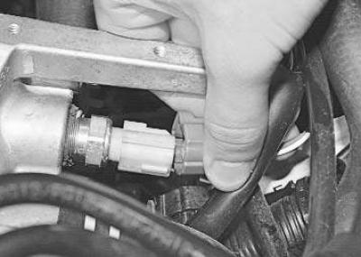
3. While pressing the latch, disconnect the block of the wiring harness from the sensor.
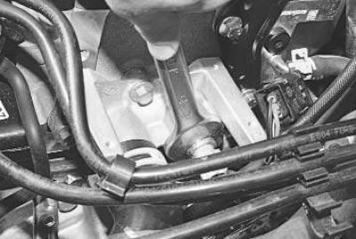
4. Loosen the tightening and turn out the coolant temperature sensor by hand.
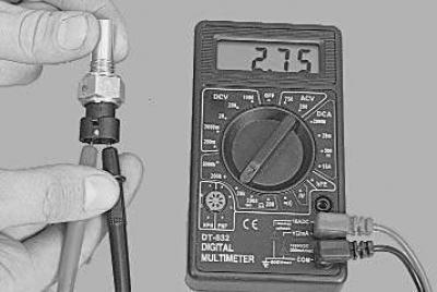
5. Connect the tester to the sensor terminals and measure the resistance, and measure the current temperature with a thermometer.
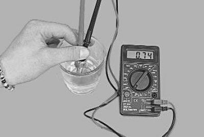
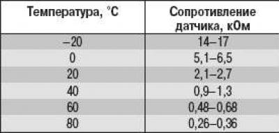
6. To measure the resistance at the sensor terminals under various temperature conditions, lower the sensor into hot water and check the change in its resistance as the water cools, controlling the water temperature with a thermometer. The nominal resistance of a good sensor is indicated in Table. 10.6.
Table 10.6. Data for checking the coolant temperature sensor
7. If the resistance deviates from the norm, replace the sensor.
8. Screw in the coolant temperature sensor and tighten it to 12 Nm.
9. Connect the wiring harness block to the sensor.
10. Fill in coolant.
Combined absolute pressure and intake air temperature sensor installed in the intake manifold.
You will need: TORX T20 key, tester, thermometer.
1. Disconnect the wire from the terminal «minus» battery.
2. Remove the air filter (see «Removal and installation of the air filter»).
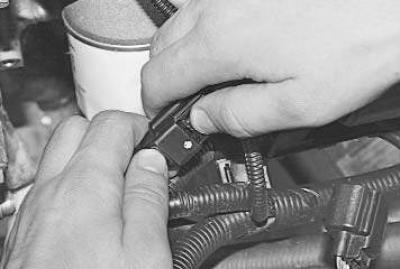
3. Press the latch..
4.... and disconnect the wiring harness connector from the sensor leads.
5. Turn out the screw of fastening..
6.... and remove the absolute pressure sensor from the intake pipe.
7. Install the new sensor in the reverse order of removal.
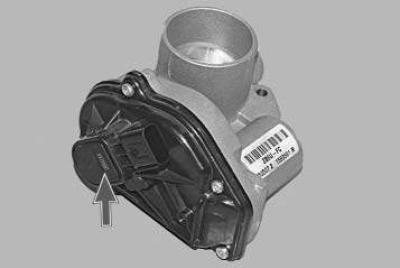
Throttle position sensor built into the throttle assembly cover, so if the sensor fails, replace the throttle assembly (see «Removal and installation of the throttle assembly»).
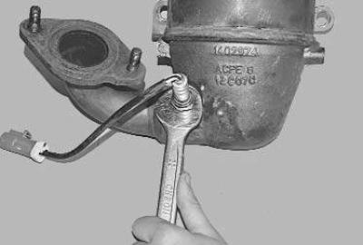
To replace the control oxygen sensor you will need a special split socket wrench «at 22».
1. Disconnect the wire from the terminal «minus» battery.
2. Remove the air filter (see «Removal and installation of the air filter»).
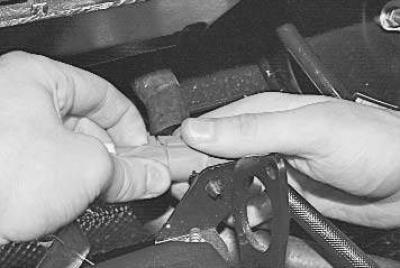
3. Squeeze the clamp of the oxygen concentration sensor harness block..
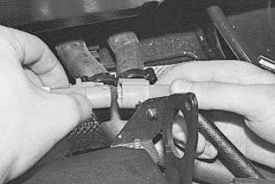
4.... and disconnect the block.

5. Install a special split key on the sensor and unscrew the control oxygen concentration sensor.
6. Install a new oxygen concentration sensor in the reverse order of removal.
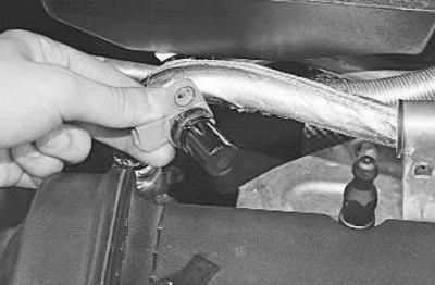
To replace the diagnostic oxygen sensor you need a key «at 22».
1. Disconnect the wire from the terminal «minus» battery.
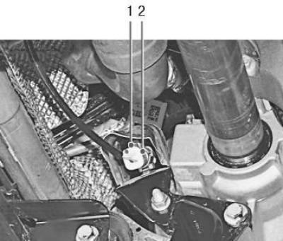
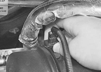
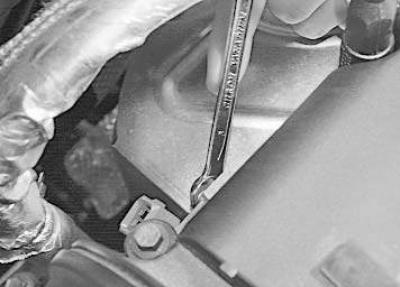
2. Remove the heat shield, remove the retainer 1 and disconnect the connector 2 of the diagnostic oxygen concentration sensor wiring harness.
3. Unscrew the sensor (for clarity, this operation is shown on the removed collector) …
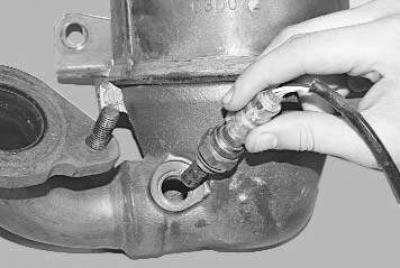
4.... and remove it from the collector.
5. Install the sensor in reverse order.
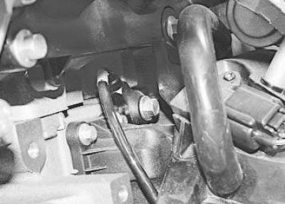
Knock sensor screwed into the wall of the cylinder block in its upper part under the intake manifold in the area of the 3rd cylinder.
You will need a key to replace the knock sensor «at 13».
1. Disconnect the wire from the terminal «minus» battery.
2. Press the latch..
3.... and disconnect the knock sensor wiring harness connector.
4. Turn out a bolt of fastening of the gauge of a detonation to the block of cylinders …
5.... and remove the sensor.
6. Install the knock sensor in the reverse order of removal.
Visitor comments