Diesel car engine Ford Scorpio 1

Diesel engines — general information
The engine with intermediate fuel injection into the combustion chamber, four-stroke, four-cylinder, in-line, water-cooled, has a camshaft in the cylinder block, mounted...
The engine with intermediate fuel injection into the combustion chamber, four-stroke, four-cylinder, in-line, water-cooled, has a camshaft in the cylinder block, mounted...
Specifications of diesel engines
Engine code (located on the cylinder block next to the dipstick) STR, N-STR, SFA, SF, 4AB, 4BA, 4CA Number of cylinders 4 in a row The order of operation of the...
Engine code (located on the cylinder block next to the dipstick) STR, N-STR, SFA, SF, 4AB, 4BA, 4CA Number of cylinders 4 in a row The order of operation of the...
Repair without removing the engine
On the engine installed in the car, you can perform the following work: removal and installation of the cylinder head; removal and installation of parts of the gas...
On the engine installed in the car, you can perform the following work: removal and installation of the cylinder head; removal and installation of parts of the gas...

Checking and adjusting valve clearances
Valve arrangement The valve clearance should be checked and, if necessary, adjusted on a cold engine after it has been in the off state for about four hours. It is...
Valve arrangement The valve clearance should be checked and, if necessary, adjusted on a cold engine after it has been in the off state for about four hours. It is...

Fuel System — Design Description
Power system diagram The system is designed to clean and supply atomized fuel to the engine cylinders in the amount necessary for the corresponding mode of operation....
Power system diagram The system is designed to clean and supply atomized fuel to the engine cylinders in the amount necessary for the corresponding mode of operation....
Nozzles — removal, inspection and installation
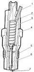
Nozzle 1 - fuel outlet channel, 2 - adjusting washer, 3 - spring, 4 - injector body, 5 - atomizer body, 6 - needle, 7 - nozzle To identify a faulty injector, follow...
Nozzle 1 - fuel outlet channel, 2 - adjusting washer, 3 - spring, 4 - injector body, 5 - atomizer body, 6 - needle, 7 - nozzle To identify a faulty injector, follow...

Glow plugs — check
Glow plug with burnt tip To check the glow plugs, disconnect the power rail from the glow plugs. Connect test lamp (any 12V light bulb) one terminal to the positive pole...
Glow plug with burnt tip To check the glow plugs, disconnect the power rail from the glow plugs. Connect test lamp (any 12V light bulb) one terminal to the positive pole...

Cylinder compression check
The compression value shows, in most cases, how worn out the cylinder-piston group of the engine. To measure compression, a compression gauge for diesel engines with a...
The compression value shows, in most cases, how worn out the cylinder-piston group of the engine. To measure compression, a compression gauge for diesel engines with a...

Bleeding air from the fuel system
This procedure must be carried out in the following cases: disconnection of the fuel pipeline; airing the fuel circuit of the fuel pump; turning off the engine in the...
This procedure must be carried out in the following cases: disconnection of the fuel pipeline; airing the fuel circuit of the fuel pump; turning off the engine in the...
Removal and installation of the fuel pump
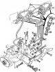
Fuel injection system 1 - high pressure fuel pump; 2 – the electromagnetic valve of a stop of the engine; 3 – holder of controls; 4 - plug; 5 – a bolt of coupling of the...
Fuel injection system 1 - high pressure fuel pump; 2 – the electromagnetic valve of a stop of the engine; 3 – holder of controls; 4 - plug; 5 – a bolt of coupling of the...

Checking and adjusting idle speed
Attention! A special tachometer is required to check the RPM of a diesel engine. Attention! Idling speed with high pressure fuel pump: DPC - 775±50 rpm; DPRC - 875±25...
Attention! A special tachometer is required to check the RPM of a diesel engine. Attention! Idling speed with high pressure fuel pump: DPC - 775±50 rpm; DPRC - 875±25...

Idle speed cable — removal and installation
To ensure stable operation of the engine when starting a cold engine and during warm-up, a special idle speed increase device is used that controls the high-pressure...
To ensure stable operation of the engine when starting a cold engine and during warm-up, a special idle speed increase device is used that controls the high-pressure...

Removing the cylinder head
Cylinder head assembly 1 - cylinder head, 2 - head gasket, 3 - swirl chamber, 4 - fixing ball, 5 - exhaust valve seat, 6 - intake valve seat, 7 - valve guides, 8 -...
Cylinder head assembly 1 - cylinder head, 2 - head gasket, 3 - swirl chamber, 4 - fixing ball, 5 - exhaust valve seat, 6 - intake valve seat, 7 - valve guides, 8 -...

Installing the cylinder head
Cylinder head gasket thickness designation Cylinder head bolt tightening sequence 1. Thoroughly clean the gasket contact surfaces in the cylinder block and head, as well...
Cylinder head gasket thickness designation Cylinder head bolt tightening sequence 1. Thoroughly clean the gasket contact surfaces in the cylinder block and head, as well...

Check and repair of a head of the block of cylinders
These procedures are performed after removing the cylinder head. Size (A) valve guide depth 1. Remove the water pump, exhaust manifold, swirl chambers, and engine...
These procedures are performed after removing the cylinder head. Size (A) valve guide depth 1. Remove the water pump, exhaust manifold, swirl chambers, and engine...
Removal and installation of the engine
Removal of the engine without gearbox is made upwards from the engine compartment using a lifting mechanism. It is also possible to remove the engine together with the...
Removal of the engine without gearbox is made upwards from the engine compartment using a lifting mechanism. It is also possible to remove the engine together with the...

Engine disassembly
Oil pump mounting elements 1. Mount the engine on a suitable frame, drain the oil and remove the oil filter. 2. Remove the vacuum pump and drive V-belt; unscrew the...
Oil pump mounting elements 1. Mount the engine on a suitable frame, drain the oil and remove the oil filter. 2. Remove the vacuum pump and drive V-belt; unscrew the...
Engine assembly — general information
Before assembling the engine, check all parts and install only clean and in good technical condition. Observe: the required connections of interacting parts, the correct...
Before assembling the engine, check all parts and install only clean and in good technical condition. Observe: the required connections of interacting parts, the correct...

Installing the rear main bearing
Numbering of main bearing caps 1. Install the gasket into the groove in the cylinder block and the rear main bearing cap. 2. Install special tool rod (21.085) on the...
Numbering of main bearing caps 1. Install the gasket into the groove in the cylinder block and the rear main bearing cap. 2. Install special tool rod (21.085) on the...

Installation of side seals
1. Unscrew the rear main bearing cap (№1) crankshaft. 2. Fit the side seals onto the rear main bearing cap, holding them with special tool 21.085 and attach the cover to...
1. Unscrew the rear main bearing cap (№1) crankshaft. 2. Fit the side seals onto the rear main bearing cap, holding them with special tool 21.085 and attach the cover to...

Assembling the piston-rod assembly
Installation of a persistent half ring of a cranked shaft 1. Check the condition of the connecting rod. 2. Observe the correct installation: the recesses on the bottom...
Installation of a persistent half ring of a cranked shaft 1. Check the condition of the connecting rod. 2. Observe the correct installation: the recesses on the bottom...

Selection of pistons by cylinder diameter
Cylinder Block Assembly 1 - cylinder block, 2 - oil pan, 3 - oil pan fastening bolt, 4 - oil drain plug, 5 - cylinder block technological hole covers, 6 - bolt, 7 -...
Cylinder Block Assembly 1 - cylinder block, 2 - oil pan, 3 - oil pan fastening bolt, 4 - oil drain plug, 5 - cylinder block technological hole covers, 6 - bolt, 7 -...

Assembly of the drive system of the gas distribution system
Gas distribution system 1 - timing chain cover, 2 - cover gasket, 3 - intermediate plate, 4 - plate gasket, 5 - camshaft sprocket, 6 - timing chain, 7 - chain tensioner...
Gas distribution system 1 - timing chain cover, 2 - cover gasket, 3 - intermediate plate, 4 - plate gasket, 5 - camshaft sprocket, 6 - timing chain, 7 - chain tensioner...
Further steps for assembling the engine
1. Install the crankshaft pulley. 2. Remove any traces of oil or grease from the crankshaft pulley mounting bolt, washer, and from the pulley-washer interface. 3. Apply...
1. Install the crankshaft pulley. 2. Remove any traces of oil or grease from the crankshaft pulley mounting bolt, washer, and from the pulley-washer interface. 3. Apply...

Turbocharger — removal and installation
Turbocharger Oil supply line to turbocharger Withdrawal 1. Remove the negative cable from the battery. 2. Remove the crankcase protection and mudguard. 3. Unscrew the...
Turbocharger Oil supply line to turbocharger Withdrawal 1. Remove the negative cable from the battery. 2. Remove the crankcase protection and mudguard. 3. Unscrew the...

Oil pump — removal and installation
Lubrication system 1 - oil pump, 2 - pump oil receiver, 3 - oil pan, 4 - drain plug, 5 - oil pan gasket, 6 - oil filter holder, 7 - oil pressure sensor, 8 - oil cooler,...
Lubrication system 1 - oil pump, 2 - pump oil receiver, 3 - oil pan, 4 - drain plug, 5 - oil pan gasket, 6 - oil filter holder, 7 - oil pressure sensor, 8 - oil cooler,...
Oil pressure check
1. Prepare an appropriate pressure gauge. 2. Warm up the engine to normal operating temperature. 3. Disconnect the oil pressure sensor from the oil filter holder and...
1. Prepare an appropriate pressure gauge. 2. Warm up the engine to normal operating temperature. 3. Disconnect the oil pressure sensor from the oil filter holder and...

Draining fluid from the cooling system
1. Unscrew the fluid filling plug in the expansion tank 2. Set the interior heating temperature control lever to the maximum temperature. 3. Unscrew the coolant drain...
1. Unscrew the fluid filling plug in the expansion tank 2. Set the interior heating temperature control lever to the maximum temperature. 3. Unscrew the coolant drain...

Filling the system and removing air
Attention! Air is removed from the cooling system automatically after the engine is started. 1. Screw in the coolant drain plug on the radiator (arrow). 2. Check the...
Attention! Air is removed from the cooling system automatically after the engine is started. 1. Screw in the coolant drain plug on the radiator (arrow). 2. Check the...
Cooling system fan
The cooling fan drive consists of two important parts - electromagnetic and friction clutches. The electromagnetic clutch is driven by a V-belt and rotates on an axle...
The cooling fan drive consists of two important parts - electromagnetic and friction clutches. The electromagnetic clutch is driven by a V-belt and rotates on an axle...

Removing and installing the fan clutch
Cooling Fan Clutch 1 - contact brush, 2 - contact ring, 3 - drive belt, 4 - coil, 5 - fan blades, 6 - bolt and nut for fastening fan blades, 7 - central nut, 8 - axle, 9...
Cooling Fan Clutch 1 - contact brush, 2 - contact ring, 3 - drive belt, 4 - coil, 5 - fan blades, 6 - bolt and nut for fastening fan blades, 7 - central nut, 8 - axle, 9...

Removal and installation of the thermostat
Thermostat 1. Drain some of the coolant from the cooling system. 2. Disconnect all pipes from the thermostat housing. 3. Unscrew the bolts securing the thermostat cover,...
Thermostat 1. Drain some of the coolant from the cooling system. 2. Disconnect all pipes from the thermostat housing. 3. Unscrew the bolts securing the thermostat cover,...
Typical engine malfunctions
Malfunction Cause Engine does not start: - starter rotates slowly The battery is not fully charged. Oxidation of battery terminals. Poor contact between body, engine and...
Malfunction Cause Engine does not start: - starter rotates slowly The battery is not fully charged. Oxidation of battery terminals. Poor contact between body, engine and...
This section is available on russian, bulgarian, belarusian, ukrainian, serbian, croatian, romanian, polish, slovak, hungarian
See other similar sections for Ford cars:
• Power unit: Fuel injection (diesel) Ford Focus Turnier 1 (1998-2004)
• Power unit: Fuel injection (diesel) Ford Mondeo 1 (1993-1996)
• Engine: Diesel engines (since 1992) Ford Escort 5 (1990-1997)
• Power unit: Fuel injection (diesel) Ford Focus Turnier 1 (1998-2004)
• Power unit: Fuel injection (diesel) Ford Mondeo 1 (1993-1996)
• Engine: Diesel engines (since 1992) Ford Escort 5 (1990-1997)
Fusion
Scorpio 1
Scorpio 2
Sierra
- General information
- Vehicle device
- User manual
- Faults on the way
- Maintenance
- Tips for the car owner
- Power unit
- Engine repair
- Lubrication and cooling system
- Supply system
- Exhaust and vapor recovery
- Transmission
- Clutch
- Car gearbox
- Front wheel drives
- Chassis
- Front suspension
- Rear suspension
- Steering
- Brake system
- Wheels and tires
- Body
- Exterior
- Interior
- Doors, locks and windows
- Body сare
- Electrical equipment
- Equipment and devices
- Engine electrics
- Lighting and signaling
- Switches and sensors
- Electrical circuits
Scorpio 1
- General information
- User manual
- Maintenance
- Power unit
- Petrol engines OHC
- Petrol engines DOHC
- Petrol engines V6
- Ignition and control
- Diesel engines
- Cooling system
- Supply system
- Carburetors
- Fuel injection
- Transmission
- Clutch
- Manual gearbox «N»
- Manual gearbox «MT 75»
- Automatic gearbox «A4LD»
- Rear axle and drive shafts
- Chassis
- Steering
- Power steering
- Front suspension
- Rear suspension
- Brake system
- Body
- Exterior
- Interior
- Doors, locks and windows
- Heating and ventilation
- Electrical equipment
- Equipment and devices
- Power devices
- Electrical circuits
Scorpio 2
- General information
- Car care
- Maintenance
- Power unit
- Engine repair
- Lubrication system
- Cooling system
- Ignition system
- Supply system
- Carburetors
- Injection system (gasoline)
- Injection system (diesel)
- Exhaust system
- Transmission
- Clutch
- Car gearbox
- Chassis
- Front suspension
- Rear suspension
- Steering
- Brake system
- Wheels and tires
- Body
- Exterior
- Interior
- Doors, locks and windows
- Heating system
- Electrical equipment
- Equipment and devices
- Headlights and lighting
- Windshield wipers and washers
- Power devices
- Electrical circuits
Sierra
- General information
- User manual
- Maintenance
- Gasoline engines
- Engine repair
- Ignition system
- Fuel system
- Cooling and lubrication system
- Changes 1984-1986
- Changes 1987-1989
- Changes 1990-1993
- Diesel engines
- Engine repair
- Fuel system
- Cooling and lubrication system
- Changes 1988-1993
- Transmission
- Clutch
- Mechanical gearbox
- Automatic gearbox
- Cardan and rear axle
- Chassis
- Steering
- Steering with power steering
- Front suspension
- Rear suspension
- Brake system
- Body and electrical
- Body elements and doors
- Electrical equipment
- Electrical circuits
FordBook.ru © 2014-2024 • Mobile version • Interesting to read • Sitemap: EN BG BY UA RS HR RO PL SK HU • Site search • Contact with administration
Focus 1 • Focus Turnier 1 • Focus 2 • Mondeo 1 • Mondeo 1 and 2 • Mondeo 2 • Mondeo 3 • Mondeo 4 • Escort 3 • Escort 4 • Escort 5 • Fiesta 2 • Fiesta 4 • Taurus 1 and 2 • Fusion • Scorpio 1 • Scorpio 2 • Sierra •
Focus 1 • Focus Turnier 1 • Focus 2 • Mondeo 1 • Mondeo 1 and 2 • Mondeo 2 • Mondeo 3 • Mondeo 4 • Escort 3 • Escort 4 • Escort 5 • Fiesta 2 • Fiesta 4 • Taurus 1 and 2 • Fusion • Scorpio 1 • Scorpio 2 • Sierra •