Fuel injection system
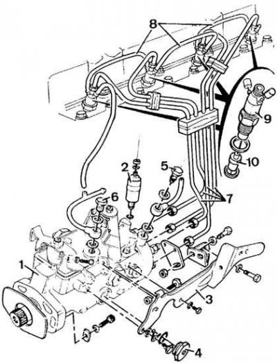
1 - high pressure fuel pump; 2 – the electromagnetic valve of a stop of the engine; 3 – holder of controls; 4 - plug; 5 – a bolt of coupling of the pipeline of giving of fuel; 6 - coupling of the return pipeline; 7 - fuel supply pipelines; 8 - return pipelines of nozzles; 9 – nozzle body; 10 - atomizer
Engines up to 1987
Withdrawal
1. Disconnect and remove the battery.
2. Remove air filter.
3. Disconnect the controls from the fuel pump, as well as the fuel return lines from the pump and from the injectors.
4. Remove the fuel supply lines to the injectors and plug their openings, disconnect the fuel supply line to the fuel pump.
5. Remove the cylinder head cover.
6. Set the piston of the 4th cylinder to TDC on the compression stroke (both valves in cylinder 1 are partially open).
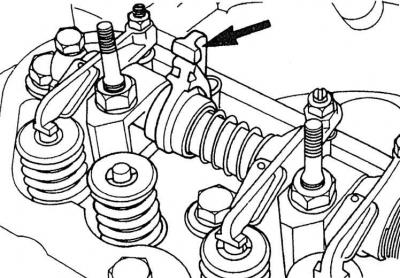
7. Using a valve spring puller together with accessories (No. 21.024, 21.024/04 and 21.024/03) compress the springs of the exhaust valve of the 4th cylinder, remove the push rod and turn the valve lever (indicated by an arrow) at 90° (install vertically).
8. Remove the sheet casing from below the engine.
9. Remove crackers, support plate and valve springs from the exhaust valve of the 4th cylinder and lower the exhaust valve to the bottom of the piston.
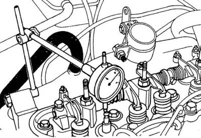
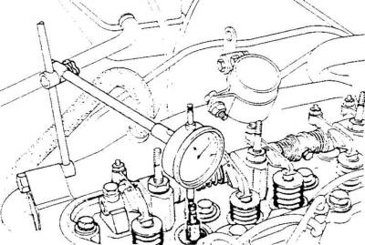
10. Install a dial indicator on the second cylinder head cover bolt and rest its measuring tip on the head of the exhaust valve stem of the 4th cylinder.
11. Check the installation of the piston of the 4th cylinder at TDC and reset the indicator.
12. Carefully turn the crankshaft in the direction opposite to the direction of its working rotation so that the exhaust valve, which rests on the bottom of the piston of the 4th cylinder, moves down by 7 mm.
13. Turn the crankshaft in the direction of its working rotation (elimination of gaps) by 4.15 mm so that the dial indicator shows a value of 2.85±0.05 mm (before TDC of the piston).
14. Unscrew the two hex bolts securing the fuel pump to the engine front cover and remove the fuel pump.
Installing the fuel pump and setting the start of injection
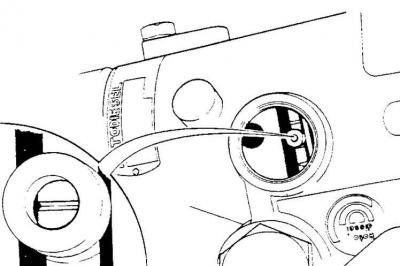
Injection mark on the fuel pump
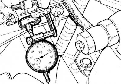
Dial indicator with holder mounted on the side of the DPA type fuel pump (in vehicles manufactured before December 1986)
1. On the side of the fuel pump, unscrew the mounting bolt and unscrew the plug that closes the control hole for setting the injection moment.
2. Rotate the pump shaft so that the mark (groove) the pump rotor was pointing up (was in the middle of the control hole).
3. Install the fuel pump and secure it with two hex socket bolts.
4. Check the installation of the pump rotor.
5. Fasten the holder together with the indicator to the side of the pump and rest the measuring tip of the indicator on the installation mark of the fuel pump rotor.
6. Turn the crankshaft in the direction opposite to the direction of its working rotation so that the piston of the 4th cylinder is 7 mm before TDC.
7. Turn the crankshaft clockwise until the indicator on the fuel pump shows the maximum value with an accuracy of 0.1–0.2 mm. This value should be 2.85±0.05 mm before TDC of the 4th cylinder piston. If this is not the case, then it is necessary to loosen the pump mounting bolts and carefully turn it.
8. Repeat the above steps, starting from setting the piston of the 4th cylinder at a distance of 7 mm before TDC, until the required value is obtained on the dial gauge.
9. Tighten the high pressure lines starting from the rear line.
10. Set the piston of the 4th cylinder to TDC and remove the tools used to set the injection advance angle.
11. Install the 4th cylinder exhaust valve springs, support plate and crackers.
12. Turn the crankshaft in the direction opposite to the direction of its working rotation until the exhaust valve of the 1st cylinder opens.
13. Insert the tappet rod of the exhaust valve of the 4th cylinder, install the lever of this valve and fix the closing plug on the fuel pump.
14. Check valve clearances and screw on cylinder head cover.
15. Connect fuel pump controls and lines.
16. Install the air filter.
17. Install the engine cover plate.
18. Install and connect the battery.
19. Remove air from the fuel system.
Engines since 1987
Removing the fuel pump on engines from 1987 is carried out in the same way as removing the fuel pump on engines up to 1987 (see higher). However, setting the fuel injection timing is different.
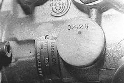
Each pump has a stopper made of artificial material, on which the installation dimension in millimeters is stamped. This size is different for each pump; measured with a Ford 23-0 extension dial gauge.
Setting value stamped on DPC pump (installed since 1987)
Unscrewing the closing plug of the fuel pump type DPC
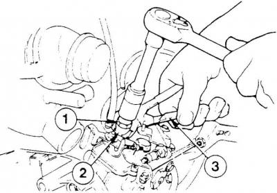
1 - closing plug, 2 - tip, 3 - pliers
Installing indicator with holder on fuel pump type DPC (in cars since 1987)
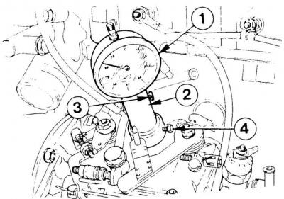
1 - dial indicator, 2 - indicator holder, 3 - indicator fixing bolt, 4 - holder fixing bolt
1. Remove the closing plug located on the pump cover.
2. Attach a dial indicator to the pump along with a Ford 23-0 extension.
3. Set the indicator so that its arrow starts to move (the measuring tip touches the pump rotor lightly).
4. Set the pump indicator needle to zero.
5. Set the piston of the 4th cylinder at a distance of 2.85±0.4 mm before TDC.
6. The pump dial indicator should immediately show the value stamped on the pump plug.
7. If this condition is not met, then loosen the fuel pump mounting bolts and very carefully turn it to one side or the other until the required indicator reading on the pump is obtained.
Visitor comments