Changes in the design 1987-1989 of the car Ford Sierra

Changes in car design from 1987 to 1989
This section applies only to changes made to Ford Sierra four-cylinder gasoline vehicles from 1987 to 1989. Specifications, as well as a description of adjustments and...
This section applies only to changes made to Ford Sierra four-cylinder gasoline vehicles from 1987 to 1989. Specifications, as well as a description of adjustments and...

OHC engine — description of changes
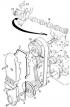
Air duct of a new type of ONS engine equipped with fuel injection A - elastic tube, B - mounting hole, C - mounting clamp Crank mechanism Pistons Since February 1987...
Air duct of a new type of ONS engine equipped with fuel injection A - elastic tube, B - mounting hole, C - mounting clamp Crank mechanism Pistons Since February 1987...

1.8 liter CVH engine — specifications
Designation 1.8 NS CVH 2V Type R2A Cylinder diameter 80 mm piston stroke 88 mm Working volume 1769 cm 3 Compression ratio 9,3 Compression pressure 1.2 - 1.4 MPa Rated...
Designation 1.8 NS CVH 2V Type R2A Cylinder diameter 80 mm piston stroke 88 mm Working volume 1769 cm 3 Compression ratio 9,3 Compression pressure 1.2 - 1.4 MPa Rated...

1.8 liter CVH engine adjustment
Engine CVH 1.8 in. 3 type R2A Valve clearance The CVH 1.8 in. 3 engine uses hydraulic tappets to automatically adjust the valve clearance.
Engine CVH 1.8 in. 3 type R2A Valve clearance The CVH 1.8 in. 3 engine uses hydraulic tappets to automatically adjust the valve clearance.

1.8 liter CVH engine ignition system
Elements of the ignition system of the CVH engine 1.8 dm sq. type R2A 1 - crankshaft V-belt pulley with toothed rim, 2 - crankshaft position and speed sensor, 3 -...
Elements of the ignition system of the CVH engine 1.8 dm sq. type R2A 1 - crankshaft V-belt pulley with toothed rim, 2 - crankshaft position and speed sensor, 3 -...
1.8 liter CVH engine timing system
CVH engine timing system 1 - upper casing of the timing system drive, 2 - lower casing of the timing system drive, 3, 4 - gaskets, 5 - crankshaft wedge pulley, 6 -...
CVH engine timing system 1 - upper casing of the timing system drive, 2 - lower casing of the timing system drive, 3, 4 - gaskets, 5 - crankshaft wedge pulley, 6 -...
1.8 liter CVH engine assembly
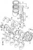
Attention! Only the difference compared to the ONS engine is shown. CVH engine crank mechanism 1 - piston with pin and piston rings, 2 - connecting rod, 3 - connecting...
Attention! Only the difference compared to the ONS engine is shown. CVH engine crank mechanism 1 - piston with pin and piston rings, 2 - connecting rod, 3 - connecting...
DOHC engine ignition system
Design and function of the ignition system Both types of DOHC engine are equipped with an electronic ignition system: engines with carburetor fuel system: ESC II...
Design and function of the ignition system Both types of DOHC engine are equipped with an electronic ignition system: engines with carburetor fuel system: ESC II...

DOHC engine fuel injection system
Elements of the Ford Motorcraft EFI DOHC engine injection system 1 - intake manifold, 2 - throttle body, 3 - air supply line to the idle air control, 4 - coolant...
Elements of the Ford Motorcraft EFI DOHC engine injection system 1 - intake manifold, 2 - throttle body, 3 - air supply line to the idle air control, 4 - coolant...
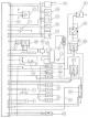
Diagram of the EEC IV system of the DOHC 2.0 liter engine
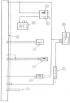
Wiring diagram of the EEC IV engine DOHC 2.0 dm 3 A - electronic control device EEC IV; B - absolute pressure sensor; C - speed sensor; E - inert switch; F - throttle...
Wiring diagram of the EEC IV engine DOHC 2.0 dm 3 A - electronic control device EEC IV; B - absolute pressure sensor; C - speed sensor; E - inert switch; F - throttle...
Checking and adjusting the EEC IV system of the DOHC engine
Diagnostics The EEC IV system has a self-diagnostic function that makes troubleshooting easier. The diagnostic connector located near the battery makes it possible to...
Diagnostics The EEC IV system has a self-diagnostic function that makes troubleshooting easier. The diagnostic connector located near the battery makes it possible to...
DOHC Engine Troubleshooting
Trouble-shooting Group Code Cause Troubleshooting Method 1 13 coolant temperature sensor – if the next code is 23 or 33, see group 6; – if the coolant temperature is too...
Trouble-shooting Group Code Cause Troubleshooting Method 1 13 coolant temperature sensor – if the next code is 23 or 33, see group 6; – if the coolant temperature is too...
Checking the elements of the EEC IV system
To check the elements of the system, disconnect the multi-pin connector from the EEC IV electronic control device, and then perform the appropriate measurements on the...
To check the elements of the system, disconnect the multi-pin connector from the EEC IV electronic control device, and then perform the appropriate measurements on the...

DOHC engine timing system
DOHC gas distribution system 1 - intake camshaft, 2 - exhaust camshaft, 3 - intake valve, 4 - exhaust valve, 5 - valve seats, 6 - valve stem seals 7 - valve springs, 8 -...
DOHC gas distribution system 1 - intake camshaft, 2 - exhaust camshaft, 3 - intake valve, 4 - exhaust valve, 5 - valve seats, 6 - valve stem seals 7 - valve springs, 8 -...
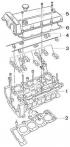
DOHC engine cylinder head
DOHC Engine Cylinder Head Assembly 1 - cylinder head, 2 - cylinder head gasket, 3 - camshaft bearing caps, 4 - oil supply pipes, 5 - cylinder head cover, 6 - cylinder...
DOHC Engine Cylinder Head Assembly 1 - cylinder head, 2 - cylinder head gasket, 3 - camshaft bearing caps, 4 - oil supply pipes, 5 - cylinder head cover, 6 - cylinder...

DOHC Engine Disassembly
DOHC engine block 1 - cylinder block, 2 - cylinder block front cover, 3 - crankshaft front O-ring, 4 - cylinder block front cover gasket, 5 - oil pan, 6 - oil pan...
DOHC engine block 1 - cylinder block, 2 - cylinder block front cover, 3 - crankshaft front O-ring, 4 - cylinder block front cover gasket, 5 - oil pan, 6 - oil pan...

DOHC Engine Assembly
In the process of assembling the engine, you should pay attention to: thorough washing of all parts; replacement of damaged (or worn) O-rings and paper gaskets;...
In the process of assembling the engine, you should pay attention to: thorough washing of all parts; replacement of damaged (or worn) O-rings and paper gaskets;...

DOHC engine lubrication system
DOHC engine lubrication system 1 - oil pump housing, 2 - oil pump propeller shaft with rotor, 3 - oil pump cover, 4 - oil pump sprocket, 5 - bypass valve, 6 - oil...
DOHC engine lubrication system 1 - oil pump housing, 2 - oil pump propeller shaft with rotor, 3 - oil pump cover, 4 - oil pump sprocket, 5 - bypass valve, 6 - oil...
Clutch specifications
Cars with DOHC engines are equipped with a clutch with a technical characteristic that is different from all other cars in this family. Clutch brand LUK, AP and Fichtel...
Cars with DOHC engines are equipped with a clutch with a technical characteristic that is different from all other cars in this family. Clutch brand LUK, AP and Fichtel...

Manual five-speed transmission type N
Since October 1986, a new design solution for the internal gear shift mechanism has been used. Internal shifter fitted in N type manual transmissions since October 1986...
Since October 1986, a new design solution for the internal gear shift mechanism has been used. Internal shifter fitted in N type manual transmissions since October 1986...
Technical data of gearbox type MT 75
Gearbox - three-shaft, classic design and has five synchronized forward gears (4th gear direct) and unsynchronized reverse gear. Installed along the car behind the...
Gearbox - three-shaft, classic design and has five synchronized forward gears (4th gear direct) and unsynchronized reverse gear. Installed along the car behind the...

Removal and installation of the gearbox type MT 75
Shafts and gears of a mechanical gearbox type MT 75 1 - needle bearing, 2 - retaining spring ring, 3 - bearing, 4 - input shaft, 5 - synchronizer ring, 6 - needle...
Shafts and gears of a mechanical gearbox type MT 75 1 - needle bearing, 2 - retaining spring ring, 3 - bearing, 4 - input shaft, 5 - synchronizer ring, 6 - needle...

Dismantling of the gearbox type MT 75
Attention! After disassembling the gearbox, all spring retaining rings should be replaced with new ones with a thickness that ensures that the required values of the...
Attention! After disassembling the gearbox, all spring retaining rings should be replaced with new ones with a thickness that ensures that the required values of the...

Inspection and repair of parts of the box type MT 75
The control dimension of the position of the end face of the selector Bearing replacement 1. Using an inertial puller, remove the bearing (3) (see fig. Shafts and gears...
The control dimension of the position of the end face of the selector Bearing replacement 1. Using an inertial puller, remove the bearing (3) (see fig. Shafts and gears...

Assembly of gearbox type MT 75
1. Insert the 1st-2nd gear fork axle onto the 1st-2nd gear synchronizer sleeve on the output shaft. 2. Compose the intermediate and secondary shafts and hold this...
1. Insert the 1st-2nd gear fork axle onto the 1st-2nd gear synchronizer sleeve on the output shaft. 2. Compose the intermediate and secondary shafts and hold this...

Automatic transmission
Caulking of the hydrokinetic transmission housing when installing the sealing ring A - caulking rod, B - traces of factory caulking, C - caulking points of a new sealing...
Caulking of the hydrokinetic transmission housing when installing the sealing ring A - caulking rod, B - traces of factory caulking, C - caulking points of a new sealing...
Front suspension
Since April 1987, the values of setting the front wheels have been changed. Changed values are shown in the table (measured in car without load). Installing the front...
Since April 1987, the values of setting the front wheels have been changed. Changed values are shown in the table (measured in car without load). Installing the front...
Specifications of the brake system
From November 1988, all versions can be equipped with an anti-lock braking system. Service brake with anti-lock system is actuated hydraulically by a dual-circuit brake...
From November 1988, all versions can be equipped with an anti-lock braking system. Service brake with anti-lock system is actuated hydraulically by a dual-circuit brake...

Maintenance and repair of the brake system
Rear disc brake 1 - caliper, 2 - caliper holder, 3 - caliper guide pin, 4 - protective cover, 5 - caliper to holder bolt, 6 - deaerator, 7 - hand brake lever, 8 -...
Rear disc brake 1 - caliper, 2 - caliper holder, 3 - caliper guide pin, 4 - protective cover, 5 - caliper to holder bolt, 6 - deaerator, 7 - hand brake lever, 8 -...
Handbrake adjustment
Attention! Handbrake adjustment is done after replacing the rear brake pads, handbrake cables or handbrake lever inside the body. In other cases, all adjustment actions...
Attention! Handbrake adjustment is done after replacing the rear brake pads, handbrake cables or handbrake lever inside the body. In other cases, all adjustment actions...
Removal of air from the brake system
Bleeding is carried out after opening the hydraulic circuits of the brakes, and also whenever the brake pedal becomes "soft" and it is necessary to press it several...
Bleeding is carried out after opening the hydraulic circuits of the brakes, and also whenever the brake pedal becomes "soft" and it is necessary to press it several...
Anti-Lock Braking System
Operating principle Braking efficiency is greatest when the grip of the tire with the road surface is maximum. During braking, the tire slides over the surface and the...
Operating principle Braking efficiency is greatest when the grip of the tire with the road surface is maximum. During braking, the tire slides over the surface and the...
Checking the functioning of the ABS
The electronic control device also implements the self-diagnosis function, warning the driver by lighting up a control light about the occurrence of a malfunction in...
The electronic control device also implements the self-diagnosis function, warning the driver by lighting up a control light about the occurrence of a malfunction in...

Hydraulic brake control unit — removal and installation
Connectors for electrical wires of the hydraulic control unit 1 - solenoid assembly connector, 2 - main solenoid valve connector, 3 - brake light sensor connector, 4 -...
Connectors for electrical wires of the hydraulic control unit 1 - solenoid assembly connector, 2 - main solenoid valve connector, 3 - brake light sensor connector, 4 -...
Wheel speed sensor
Replacing the front wheel speed sensor 1. Loosen the nuts securing the respective front wheel. 2. Raise the car and remove the wheel. 3. Unscrew the rotation sensor...
Replacing the front wheel speed sensor 1. Loosen the nuts securing the respective front wheel. 2. Raise the car and remove the wheel. 3. Unscrew the rotation sensor...
Generator and starter — specifications
Generator A generator with a built-in electronic regulator is used. Make and type: Bosch N1-31/70 A, Bosch K1-23/55 A, Lucas A1-33/55 A or Bosch N1-34/90 A....
Generator A generator with a built-in electronic regulator is used. Make and type: Bosch N1-31/70 A, Bosch K1-23/55 A, Lucas A1-33/55 A or Bosch N1-34/90 A....
General data and vehicle characteristics
Dimensions body sedan (4-door). Full length: 4.467 m. Full width: 1.698 m. Front overhang: 0.801 m. Rear overhang: 1.058 m. Wheelbase: 2.608 m. Front wheel track: 1.452...
Dimensions body sedan (4-door). Full length: 4.467 m. Full width: 1.698 m. Front overhang: 0.801 m. Rear overhang: 1.058 m. Wheelbase: 2.608 m. Front wheel track: 1.452...
This section is available on russian, bulgarian, belarusian, ukrainian, serbian, croatian, romanian, polish, slovak, hungarian
Fusion
Scorpio 1
Scorpio 2
Sierra
- General information
- Vehicle device
- User manual
- Faults on the way
- Maintenance
- Tips for the car owner
- Power unit
- Engine repair
- Lubrication and cooling system
- Supply system
- Exhaust and vapor recovery
- Transmission
- Clutch
- Car gearbox
- Front wheel drives
- Chassis
- Front suspension
- Rear suspension
- Steering
- Brake system
- Wheels and tires
- Body
- Exterior
- Interior
- Doors, locks and windows
- Body сare
- Electrical equipment
- Equipment and devices
- Engine electrics
- Lighting and signaling
- Switches and sensors
- Electrical circuits
Scorpio 1
- General information
- User manual
- Maintenance
- Power unit
- Petrol engines OHC
- Petrol engines DOHC
- Petrol engines V6
- Ignition and control
- Diesel engines
- Cooling system
- Supply system
- Carburetors
- Fuel injection
- Transmission
- Clutch
- Manual gearbox «N»
- Manual gearbox «MT 75»
- Automatic gearbox «A4LD»
- Rear axle and drive shafts
- Chassis
- Steering
- Power steering
- Front suspension
- Rear suspension
- Brake system
- Body
- Exterior
- Interior
- Doors, locks and windows
- Heating and ventilation
- Electrical equipment
- Equipment and devices
- Power devices
- Electrical circuits
Scorpio 2
- General information
- Car care
- Maintenance
- Power unit
- Engine repair
- Lubrication system
- Cooling system
- Ignition system
- Supply system
- Carburetors
- Injection system (gasoline)
- Injection system (diesel)
- Exhaust system
- Transmission
- Clutch
- Car gearbox
- Chassis
- Front suspension
- Rear suspension
- Steering
- Brake system
- Wheels and tires
- Body
- Exterior
- Interior
- Doors, locks and windows
- Heating system
- Electrical equipment
- Equipment and devices
- Headlights and lighting
- Windshield wipers and washers
- Power devices
- Electrical circuits
Sierra
- General information
- User manual
- Maintenance
- Gasoline engines
- Engine repair
- Ignition system
- Fuel system
- Cooling and lubrication system
- Changes 1984-1986
- Changes 1987-1989
- Changes 1990-1993
- Diesel engines
- Engine repair
- Fuel system
- Cooling and lubrication system
- Changes 1988-1993
- Transmission
- Clutch
- Mechanical gearbox
- Automatic gearbox
- Cardan and rear axle
- Chassis
- Steering
- Steering with power steering
- Front suspension
- Rear suspension
- Brake system
- Body and electrical
- Body elements and doors
- Electrical equipment
- Electrical circuits
FordBook.ru © 2014-2024 • Mobile version • Interesting to read • Sitemap: EN BG BY UA RS HR RO PL SK HU • Site search • Contact with administration
Focus 1 • Focus Turnier 1 • Focus 2 • Mondeo 1 • Mondeo 1 and 2 • Mondeo 2 • Mondeo 3 • Mondeo 4 • Escort 3 • Escort 4 • Escort 5 • Fiesta 2 • Fiesta 4 • Taurus 1 and 2 • Fusion • Scorpio 1 • Scorpio 2 • Sierra •
Focus 1 • Focus Turnier 1 • Focus 2 • Mondeo 1 • Mondeo 1 and 2 • Mondeo 2 • Mondeo 3 • Mondeo 4 • Escort 3 • Escort 4 • Escort 5 • Fiesta 2 • Fiesta 4 • Taurus 1 and 2 • Fusion • Scorpio 1 • Scorpio 2 • Sierra •