Calking of the hydrokinetic transmission housing when installing the sealing ring
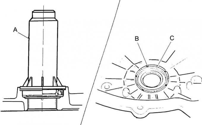
A – calking rod, B – traces of factory calking, C – points of calking of a new sealing ring
Since May 1986, the oil pump seal ring has been fixed by calking the hydrokinetic transmission housing.
Vacuum Regulator Unit for Shifting
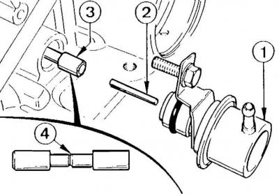
1 – vacuum regulator, 2 – pusher, 3 – valve, 4 – valve identification groove
Since June 1988, a new vacuum shift regulator valve has been used with the designation: 84 GT 7D 080 BA. It can be identified by the groove in the middle section (4).
Automatic transmission brake band adjustment bolts
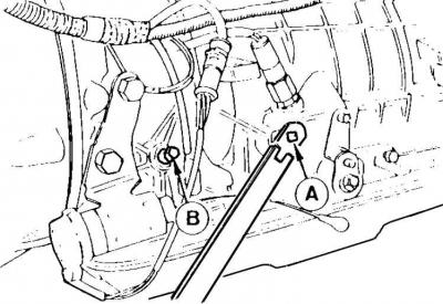
A – middle brake band adjustment bolt,
B – Front brake band adjustment bolt
Since August 1988, the method of adjusting the automatic transmission brake bands has been changed:
– the bolt (A) for adjusting the middle brake band must be unscrewed (after being fully screwed in) by 2.5 turns;
– the bolt (B) for adjusting the front brake band must be unscrewed (after being fully screwed in) by 2 turns.
Modified shape of the automatic transmission oil pan
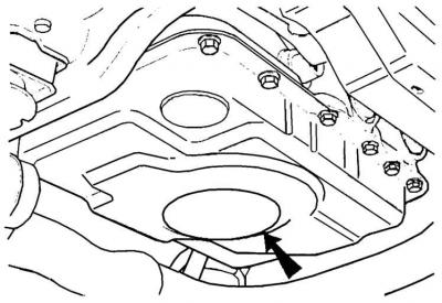
The arrow indicates the modified shape of the pallet.
Since the 1989 model, automatic transmissions have been equipped with reshaped oil pans and oil pumps with a longer oil pickup.
From factory code 8K24, automatic transmissions have magnetic oil pans.
Automatic transmission Ford A 4 LD
In April 1989, electrohydraulic control of the gearbox was introduced with blocking of the hydrokinetic transmission by the system for engaging 3rd and 4th gears.
The hydrokinetic transmission clutch is locked by the EEC IV electronic control unit. This clutch is unlocked each time the brake pedal is pressed.
The transition from 3rd to 4th gear is provided by an additional electromagnetic valve, controlled by the electronic control unit EEC IV.
The shift point from 4th to 3rd gear (gear reduction) is optimised based on the driving speed, engine load and accelerator pedal position.
After pressing the accelerator pedal to the stop (kick-down), the electronic device controlling the automatic transmission causes:
- hydrokinetic transmission locking while driving in 3rd gear at 130 km/h;
- gear shift from 3rd to 4th at a speed of over 6100 rpm;
- gear reduction from 4th to 3rd when the engine speed is less than 4200 rpm.
Adjusting the gear reduction cable (kick-down mechanism)
1. Turn on the ignition, press the accelerator pedal all the way down and hold it in this position.
2. Turn the automatic transmission kick-down lever counterclockwise until it stops.
3. Install the Ford 17.031 tool onto the cable to prevent it from becoming over-tensioned.
4. Loosen the solenoid valve mounting bolts.
5. Move the solenoid valve to the forward position where significant resistance is felt.
Caution! If the solenoid valve is moved too far, the cable will become loose. In this case, move the valve back and repeat the previous operations.
6. Tighten the lower mounting bolt first and then the upper bolt to the appropriate torque.
7. If the adjustment is correct, the solenoid valve should hold the kick-down mechanism lever at a distance of 0.3–0.8 mm clockwise from the extreme position.
8. If the cable is too tight, the electromagnetic valve will not reach the correct position and the lever will return to its previous position after passing through the magnet. The cable tension adjustment should be repeated.
Other information regarding the technical characteristics, adjustment and repair of the automatic transmission is given in subsection 6.3 (Ford C3 gearbox) and in subsection 3.1.3.15 (Ford A 4 LD gearbox).
Content was created using data from this website fordbook