- thorough washing of all parts;
- replacement of damaged (or worn) sealing rings and paper gaskets;
- compliance with the appropriate tightening torques for threaded connections;
- using new cylinder head bolts and tightening them in the correct sequence;
- compliance with the correct combinations of interacting elements (they must be in the same places in which they were located before disassembling the engine).
DOHC engine piston bottom markings
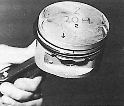
The arrow on the bottom of the piston during installation must be directed towards the valve timing drive (towards the front of the engine).
DOHC Engine Connecting Rod Cap Designation
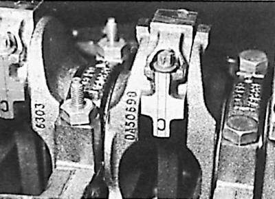
The top figure shows the complete set with a connecting rod.
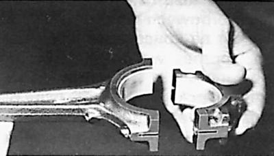
The figure below shows the correct position of the cover relative to the connecting rod.
Measuring the piston clearance in the cylinder
1. Install the main bearing caps without the liners and tighten their mounting bolts to the required torque.
2. Turn the engine 180° (cylinder holes facing up).
3. Measure the cylinder diameters. If these diameters exceed the corresponding values (see subsection 3.1.4.3.1.2), the cylinders should be reground to the repair size or the engine cylinder block should be replaced and the corresponding pistons should be selected.
4. Remove the main bearing caps.
Measuring the clearance in the main bearings of the crankshaft
1. Insert the liners into the cylinder block main bearing seats.
2. Install the crankshaft in the bearings.
3. Place a Plastigage measuring rod of a length equal to the width of the bearing along the main journal in which the clearance is to be measured, put on the corresponding main bearing cap together with its bearing cap and tighten the cap mounting bolts to the required torque.
Caution! Do not rotate the crankshaft during this operation.
4. Remove the main bearing cap together with its shell.
5. Compare the width of the deformed measuring rod with the scale supplied with the rod and determine the journal clearance in the bearing on this basis. If the clearance exceeds the permissible limits, the main bearings should be replaced.
Engine assembly
1. Install the main bearing shells into the engine cylinder block seats (do not lubricate the outer surface of the shells with oil).
2. Lubricate the sliding surface of the main bearing shells with engine oil and install the crankshaft in the main bearings.
3. Put on the main bearing caps (the arrow on the cap points towards the front of the engine) together with their liners (with the sliding surface also lubricated with engine oil) and insert the crankshaft thrust half rings into the middle main bearing seats.
4. Install a micrometer indicator to the crankshaft axis to measure the shaft axial play.
5. Using a screwdriver, move the crankshaft longitudinally within the axial clearance and read the indicator readings.
6. Compare this value with the correct value (see subsection 3.1.4.3.1.3).
7. If necessary, replace the crankshaft thrust half rings with half rings of the required thickness to ensure the correct axial clearance of the crankshaft and check this clearance again.
8. Check the piston ring gap after installing them in the engine cylinders. If necessary, replace the rings that have an incorrect gap.
9. Place the tested rings on the pistons.
10. Place the ring locks evenly around the perimeter of each piston. This also applies to the elements of the oil scraper ring in relation to its expander (spring).
11. Insert the pistons together with the connecting rods into the engine cylinders. The arrow on the bottom of the piston should point towards the valve timing drive (towards the front of the engine).
12. Insert connecting rod bearings with a sliding surface lubricated with engine oil into the lower heads of the connecting rods.
13. Install the connecting rod caps together with the bearing shells, screw in the new bolts and tighten the connecting rod bolts to the specified torque.
14. Check the axial clearance of the connecting rods on the crankshaft journals.
15. Press the new gearbox input shaft bearing into the hole in the end of the crankshaft.
16. Remove the rear crankshaft seal ring from the rear cylinder block cover.
17. Screw the rear cover to the engine block.
18. Lubricate the lip of the new crankshaft seal with engine oil and install it on the rear cylinder block cover using the plate and two flywheel mounting bolts (the inner diameter of the plate must be larger than the shaft diameter being sealed, and the outer diameter must be equal to the outer diameter of the rear seal ring).
19. Screw the front cover to the cylinder block together with a new gasket.
20. Screw the oil pan partition (oil deflector) and the oil pump oil receiver and mesh with a new gasket to the cylinder block from below.
21. Install the oil pan with a new gasket, tightening the mounting bolts to the required torque.
22. Screw the flywheel to the crankshaft with new bolts.
23. Center the clutch disc and attach the clutch drive portion to the flywheel.
24. Screw on the crankshaft position sensor and oil pressure sensor.
25. Install the oil pump (see subsection 3.1.4.4.11).
26. Install the oil filter and coolant pump on the cylinder block.
27. Install the cylinder head gasket.
28. Set the piston of the 1st cylinder at a distance of about 20 mm from TDC.
29. Install the cylinder head, screw the new head mounting bolts into the holes and tighten them in the appropriate manner (for a description of installing the cylinder head, see subsection 3.1.4.4.8).
30. Lubricate with oil and install hydraulic tappets in the guides.
31. Lubricate the camshaft bearings with engine oil and install both shafts on them.
32. Install the camshaft bearing caps and tighten their bolts to the appropriate torque.
33. Install the sprockets and timing chain (see subsection 3.1.4.4.7).
34. Install the upper chain guide.
35. Install the chain and sprocket of the oil pump drive.
36. Install the oil pump chain tensioner.
37. Install the key into the crankshaft groove.
38. Install the lower cover of the cardan shaft of the timing chain.
39. Install the crankshaft torsional vibration damper, center the lower casing of the cardan chain of the valve timing system and tighten its bolts to the appropriate torque.
40. Put on the upper cover of the cardan chain of the timing system, paying attention to the placement of its gasket, and tighten the bolts of its fastening to the appropriate torque.
41. Install the cylinder head cover together with a new gasket, tightening its mounting bolts to the appropriate torque.
42. Screw in the cooling system drain plug together with a new gasket.
43. Screw in the spark plugs, connect the high-tension wires and screw on their holder.
44. Install the crankcase ventilation system pipes.
45. Install the generator, put on the V-belt for the generator and coolant pump drive and adjust its tension.
46. Fill the engine with the required amount of the appropriate oil and insert the oil level indicator.
[The original can be found on the specified resource FordBook]