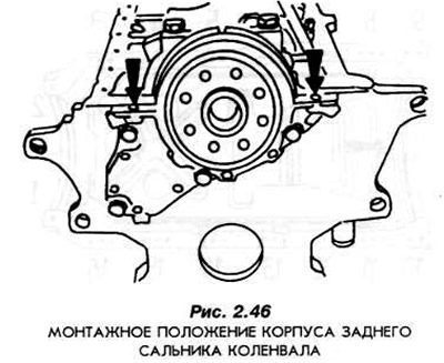
Install the new seal as follows:
- generously lubricate the crankshaft journal and oil seal lips.
- install the seal on the guide 21-011 E.
- install guide 21-011 E so that its two holes coincide with the two threaded holes in the crankshaft flange.
- lightly tap the guide with the seal with a hammer until it is possible to screw the guide to the crankshaft flange with two M10x1x38 bolts.
- tighten the bolts so that the guide fits snugly against the shaft.
- remove the guide.
Install the front cover using tool 21-148 to center it (Fig. 2.47).
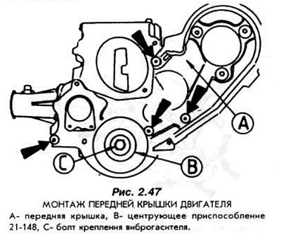
Install the new seal using tool 21-148. The seal must be inserted into the socket until it stops.
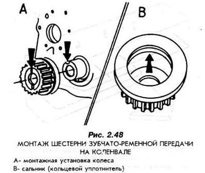
Install the gear on the front crankshaft journal. The projection on the crankshaft journal should be in the gear groove (Fig. 2.48).
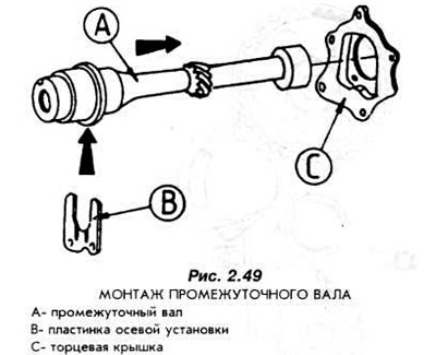
Install the intermediate shaft with the axial installation washer.
The groove in the washer should be visible from the front of the engine (Fig. 2.49).
Install the oil pan with a new gasket (Fig. 2.50).
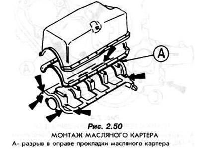
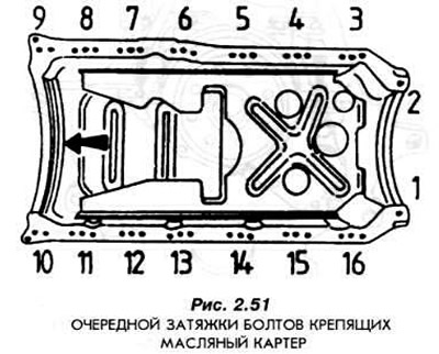
Pay attention to the correct installation of the gasket. First, firmly tighten the bolts on the corners of the oil pan by hand (1, 2, 9, 10 Fig. 2.51). Then tighten bolts 3-8 and 11-16, as well as the corner bolts.
Install the water pump.
Install a new intermediate shaft seal housing. The seal is a single unit with the housing and is not replaceable. Install the housing together with the plastic seal (sealing ring) inside it.
Screw the oil pump with a new gasket to the engine body. Before installation, fill the pump with about 10 cm³ of engine oil.
Screw on the oil filter by hand with a well-lubricated gasket.
Measure the piston protrusion using an indicator.
The amount of protrusion of each piston must be measured when it is at TDC. To measure this, the indicator must be installed on the upper plate of the engine housing, as shown in Fig. 2.52.
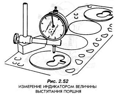
The amount of protrusion of each piston must be measured at two points located opposite each other on the axis of the piston pin. The measuring tip of the indicator must be placed at a distance of 5 mm from the edge of the piston bottom.
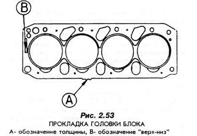
Select a new head gasket according to the data given in section 1.1 (Fig. 2.53). Degrease the block preparation seating surface (the surface where the gasket fits onto the block head).
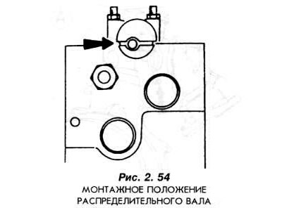
Set the crankshaft to a position where the pistons of the first and fourth cylinders are at TDC.
Install the camshaft according to Fig. 2.54.
Place the cylinder head gasket on the plane of the engine housing.
Place the cylinder head and screw it on with new bolts (Fig. 2.55).
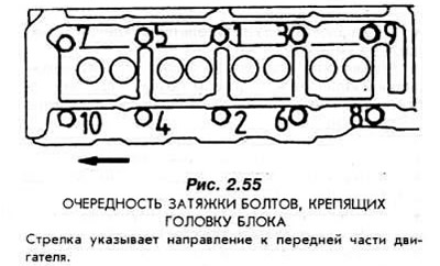
The bolts securing the cylinder head are tightened in the following manner:
- Stage I: 20-30 Nm.
- Stage II: 76-92 Nm.
- wait at least 2 minutes.
- Step III: Turn the bolts 90°.
There is no need to additionally tighten the bolts securing the cylinder head after a certain period of operation has elapsed.
Screw in the spark plugs.
Install the electrical wiring harness.
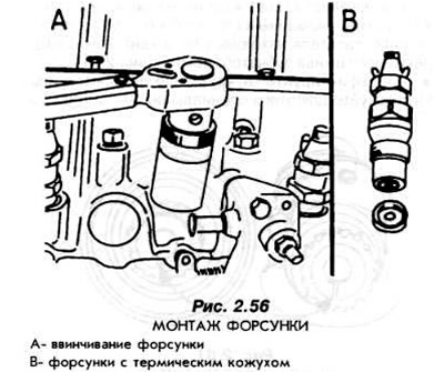
Screw in the injectors using the GV-2304 key (Fig. 2.56). Use new thermal covers for the sprayers.
Screw the thermostat housing to the cylinder head.
Connect the flexible hose to the water pump and thermostat.
Install a coolant flow branch pipe.
Note: The flexible hose of the cooling system is connected to the pump in such a way that the white mark on the hose coincides with the lug on the pump nipple.
Install the generator bracket.
Secure the generator clamp.
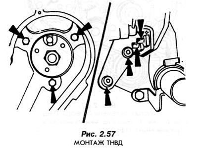
Screw the fuel injection pump to the front wall of the engine housing (Fig. 2.57).
Connect the high pressure fuel pipes connecting the injection pump to the injectors.
Install overflow fuel lines to drain excess fuel from the injectors.
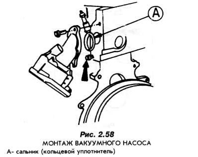
Install the vacuum pump according to Fig. 2.58:
- screw in the bottom bolt
- install a pump on it.
- screw in the top bolt.
- tighten both bolts evenly.
Connect the excess fuel overflow tube.
Screw on both bottom metal covers covering the toothed belt.
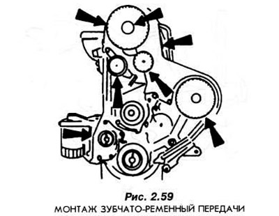
Install: Timing Belt Pulley, Drive Timing Belt, Mounted on Crankshaft; drive belt pulley mounted on the camshaft; and also a toothed belt (Fig. 2.59):
- install the gear on the camshaft journal,
- install the belt pulley that drives the fuel injection pump (find the elongated holes on this wheel),
- set the belt tensioner to the initial tension,
- install the belt pulley on the intermediate shaft, correctly seating it on the mounting pin,
- install the camshaft and fuel injection pump pulleys in such a way that their holes or recesses coincide with the holes in the cylinder head or in the pump body,
- insert installation rod 23-019 (camshaft and CAV pump) or 23-029 (BOSCH pump).
Note: If the fuel system is equipped with a CAV pump, a new 6 mm diameter drill bit with a cylindrical rod must be inserted into the elongated hole of the belt pulley.
Screw in the 21-104 setting pin, which serves to indicate TDC. The pin must be screwed in until it stops and the crankshaft must touch it.
Install the new fuel injection pump drive toothed belt in such a way that the tension side of the belt is taut (Fig. 2.60).
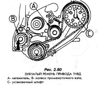
Loosen the bolt securing the timing belt tensioner by half a turn. The tensioner will "bounce" toward the timing belt and tighten it.
Note: When installing the timing belt, pay attention to the direction of transmission movement.
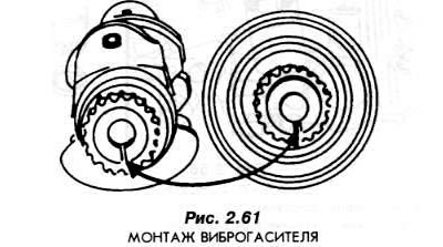
Screw in the TDC setting pin. Screw in the vibration damper using new bolts.
Note: When installing the belt pulley, make sure that the protrusion on the vibration damper hub is in the groove of the toothed belt pulley hub (Fig. 2.61).
Fix the vibration damper from rotating. Use the special device 15-030 A for this.
Screw in the TDC setting pin again and lock the crankshaft in this position (TDC).
Install a new timing belt. The pull side of the belt must be taut.
Loosen the timing belt tensioner, the tensioner will move towards the belt and tighten it.
After this, secure the tensioner again.
Remove all dowel pins. Rotate the crankshaft two revolutions in the direction of rotation during engine operation. The elongated hole in the fuel injection pump belt pulley must be set to the 12 o'clock position. Then move it to the 11 o'clock position.
In this position, screw in the TDC setting pin.
Carefully turn the crankshaft in the direction of rotation while the engine is running and bring it to the correct position relative to the installation pin at TDC (Fig. 2.43).
Place the dowel pins in the camshaft pulley and the injection pump pulley. If the vehicle is equipped with a CAV injection pump, a 6 mm drill pin must be used.
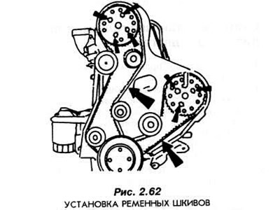
Loosen the bolts securing the belt pulleys by half a turn and tighten both belts on the side opposite the tensioner. Release the pressure on the belts. Tighten all the bolts again (Fig. 2.62). Remove all the dowel pins.
Unscrew the TDC setting pin from the housing.
Install the upper and lower camshaft drive belt covers.
Pay attention to the good fit of the nut that secures the water pump. If necessary, use "Loctite-242" to seal it.
Install and tension the alternator drive V-belt.
Install the generator casing.
Screw the flywheel on with new bolts.
Adjust the valve clearances as described in section 2.4 "Cylinder Head".
Install the cylinder head cover.
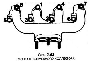
Install the intake and exhaust manifolds (Fig. 2.63).
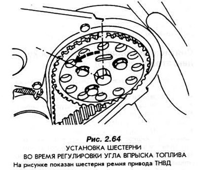
Set the start of fuel injection in the high-pressure fuel pump.
Turn the crankshaft to the position shown in Fig. 2.64.
Screw the TDC pin into the engine housing and turn the crankshaft toward that pin. Turn the shaft in the direction that corresponds to its direction of rotation when the engine is running.
Insert the 23-029 or 23-019 dowel pin through the hole in the fuel injection pump drive belt pulley and through the hole in the front plate of the engine housing into the hole in the pump drive connection flange. The pin should fit freely into the holes. It should also be possible to insert it as far as the end of its length.
If this cannot be done, loosen the belt pulley mounting bolts and turn the injection pump so that the installation pin can be inserted into the holes without any difficulty. After completing the adjustment, tighten the injection pump drive gear bolts firmly.
[The material was copied from an information website: FordBook.ru]